UK Monster Owners Club Forum » .: Technical :. » Mods & How To's » Slow Monster rebuild

Reply
 
Thread Tools Display Modes
Old 09-03-2019, 04:40 AM   #871
350TSS
Too much time on my hands member
 
350TSS's Avatar
 
Join Date: Jan 2013
Location: Shipbourne
Bike: M900
Posts: 1,419
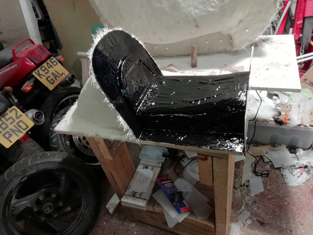
Both sides of the tank top mould are now done with 4 layers of 300g mat, just the little bit at the front around the key switch to do to finish the top surface mould. I will need to drill the flanges every 50mm and put some 6mm nuts and bolts through so that the mould goes back in exactly the same place when it is taken apart to remove the pattern and put back together in preparation for the CF. Then the tank underside can be done, hopefully in one piece but I will not really know that until I turn it over.
diesel station near me

Whilst waiting for the various coats of resin on the tank mould to cure I turned my attention to the seat pattern and in particular the mould divider. I originally intended to split the mould longitudinally along the centre-line but decided that it would be a lot easier to do it laterally just aft of the start of the seat hump. This has the added advantage that the inevitable flash line will be hidden beneath the seat upholstery.
I was about to start fixing the divider to the pattern when it dawned on me that when extending the length of the seat pattern and providing a more sculptured base I had completely forgotten about the interface between the tank and the seat base (originally a simple butte joint). I had become obsessed with making the seat base look less like a plank and had spent a lot of effort raising the front and providing curved profiles towards the front of the seat base. The result was that the leading edge had grown 25mm to 30mm in height and width. If I had moulded it from that modified pattern it would have looked like additional air scoops immediately aft of the tank.
The heavy duty blacksmith’s rasp was pressed into service to reduce the width of the carefully sculpted and laboriously rubbed down front profile of the seat by about 25mm. The seat base now looks like a plank again, a curved plank but still a plank, this took about 2 hours and was a bit heart breaking.

Due to a basic original design flaw (not considering the thickness of foam and upholstery at the front of the seat when making the seat base) whatever happens there will be a slight aesthetic disconnect at the junction between the tank and the seat. The tank has near vertical sides with the rear outer edges tangential to the outer width of the frame rails with virtually no overhang beyond the frame rail width. The sides of the seat base have to/currently sit outside the frame rails and the width of the seat moulding has to allow for the thickness of:
a) the CF of the seat base itself,
b) any foam on the outside of seat base at the front,
c) the ambla seat upholstery on the outside and
d) the ambla on the inside of the seat base and any mechanical fixing to the seat base (contact adhesive or the hook and loop parts of Velcro tape?).
This is an absolute minimum of 6mm step each side assuming no foam whatsoever at the front on the sides. I originally intended to have 6mm closed cell rubber foam on either side of the seat flanks, I could try to taper this towards the leading edge but think that any abrasive applied to this type of foam will cause it to grip and tear. Plastic foam might work but is nowhere near as good, some experimentation is required.
350TSS is offline   Reply With Quote
Old 12-03-2019, 06:27 PM   #872
350TSS
Too much time on my hands member
 
350TSS's Avatar
 
Join Date: Jan 2013
Location: Shipbourne
Bike: M900
Posts: 1,419
On the tank top the two large halves are now bolted together and the ignition switch cut-out is now gel coated.
The seat mould divider has now been attached (hot glue gunned) and the first mould gel coat applied to one half of the mould.
chase branch bank near me
There are two consequences of lengthening the seat by 50mm, the first is that this:


which I made very early in the project from 3mm aluminium will no longer fit as the mounting pick up points onto the residual tea tray frame tubes are now 50mm adrift, the second is that my number plate has a distinctly better chance of avoiding a collision with the rear wheel on full bump.
I will re-design the component to make it in CF but it will definitely not be an easy pattern/ mould to make. I suspect that given that I do not yet know the exact location of the seat it would make sense to manufacture it in 2 parts; a) the rear light/camera holder to be attached to the seat hump and b) the number plate holder /rear seat hump support structure attached to the frame. I am sure I can save at least 150g by going to CF from aluminium if I get the design right. Readers will be pleased to note that I am almost certain there are now no further possible CF components that I can make for the bike.
I also spent some time today cutting cotton patterns, (subsequently transferred to cardboard) for the other CF moulds.
Whilst looking for something else I got distracted and found the oil pump which I then stripped, it was spotless inside with just some witness marks (probably less than 0.001”) where the gears run against the retaining plate. I lapped these out on a surface plate with some 240/600 wet and dry and after thoroughly cleaning everything with paraffin I torqued the 6 x 6mm socket cap screws back up again (9Nm) and sealed it in a plastic bag.
350TSS is offline   Reply With Quote
Old 16-03-2019, 06:19 AM   #873
350TSS
Too much time on my hands member
 
350TSS's Avatar
 
Join Date: Jan 2013
Location: Shipbourne
Bike: M900
Posts: 1,419
I finished the tank top mould yesterday and once it was cured had to separate it from the stand it was on.
Up until the tank mould I have been using Easy Composites for all the CF and GF resin and matting supplies. It is good stuff but EC are at the top end of the market for price. Their polyester resin is sea water green and translucent and quite viscous, think EP90. I shopped around for polyester resin and bought some cheaper stuff which is cream coloured and much less viscous, think 10W fork oil. Aside from the price benefit it is much easier to wet the glass mat and seems better at resisting the formation of air pockets when stippling the resin. The downside is that it runs everywhere and on the tank mould with near vertical sides resin puddles formed naturally at the bottom of the tank sides at the junction with the base board. It took about 2 hours with a wood chisel to separate the mould from the base.
From a cursory inspection (and without separating the three parts of the top mould) it looks as though the tank top mould has come out well with the flanges nice and flat and well defined. I also think that the tank bottom mould can be done as one piece.
Picture below shows mould just as I turned it over with all the debris from releasing it still in it
exxon station near me
What has become evident though is that my original planned scheme to bond the tank top to the bottom will not work. If I had thought about it for more than a nano-second then it was blindingly obvious that it would never have worked as when the two halves are introduced to each other there will be a very fine single point of contact between them which will not bode well for either strength or juice retention capability.
It is clear that I will have to form a “ledge” about 10 to 20mm wide on the inside of the tank top marrying accurately with the profile of the tank bottom about 5mm above the bottom edge of the tank. When the tank bottom is formed it will have to be cut about 0.5mm undersize so that it fits inside the tank top and sits comfortably and consistently on this ledge. This is not going to be easy and as I sit now I have no real clue as to how to do it. The underside of the tank at the junction with the tank top along both flanks is semi-circular to accommodate fitting over the frame rails, it is only at the front and back that a right angled “ledge” is possible.
The other possibility is to mould the tank bottom and form an “up stand” all around the base mould that marries with the profile of the inside of tank top.
On balance the “ledge” appears a better solution as it will be easier to ensure that contact between the two halves is complete and that resin contact between them is continuous but forming it accurately along the edge of the underside of the tank top will be a significant challenge.
The hump part of the seat mould is now complete and a first gel coat has been applied to the seat part.

Work continues with cutting cotton patterns for the CF to go into the moulds
350TSS is offline   Reply With Quote
Old 18-03-2019, 08:11 AM   #874
350TSS
Too much time on my hands member
 
350TSS's Avatar
 
Join Date: Jan 2013
Location: Shipbourne
Bike: M900
Posts: 1,419
The seat base mould now has 4 coats of 300g mat the divider has been drilled and bolted and and the complete mould is nearly ready for separation from the base plate. I am a bit worried that the seat contour might form a mechanical lock but we will give it a go tomorrow when the resin has fully cured
With both brain cells working overtime I think I now have a cunning plan for:
a) the formation of the ledge to locate the tank bottom mould and to provide a good sealing “gasket” face to bond to, and
b) the clear strip in the tank top mould acting as a fuel gauge (the idea has had a resurrection as I think I have a way of doing it which will not be adversely affected when I put the anti-ethanol resin in the tank after joining the top and bottom halves together).
Still exercising both cells is how to brace/baffle the inside of the tank. It dawned on me that if the tank holds 25 litres of fuel (ish) then that would be 25 kilos if it held water and about ¾ of that if it holds petrol - say up to 18 kilos. I would like to reinforce the internal structure around the mid mounting points on the bottom of the tank to spread the load but need to ensure that when I put the bottom of the tank in that the reinforcing structure actually is in contact with the top and the sides and is capable of being securely bonded in.
I picked up one of these on fleabay (from China) for the princely sum of £1.71 delivered.


I did not expect it to work but it does – it will fit in the petrol tank overflow pipe that will emerge from the little expansion hump in front of the filler cap
350TSS is offline   Reply With Quote
Old 18-03-2019, 12:48 PM   #875
utopia
No turn left unstoned
 
utopia's Avatar
 
Join Date: Jun 2010
Location: leicester
Bike: M750
Posts: 4,545
Is that a non-return breather valve ? ..... from China, and it actually works ?
That's a rare bird.
I've bought a couple of those from different sources recently and both of them did absolutely bugger all.
utopia is offline   Reply With Quote
Old 18-03-2019, 05:24 PM   #876
Mr Gazza
Lord of the Rings
 
Mr Gazza's Avatar
 
Join Date: May 2013
Location: Norwich
Bike: M900sie
Posts: 5,790
Am I missing something obvious here ? Or is it that a non-return valve is counter productive on a tank breather and pointless on an overflow?

The tank has to breathe out when sitting in the Sun or anywhere else warmer than where it has just been.. And in when the level goes down in use. It's a two way flow.

The valve must allow fuel outwards on an overflow, but what exactly is it preventing from returning if the hose is routed far enough downwards?

Sweet little valve though... There must be somewhere you can use it.
__________________
Mr Gazza is offline   Reply With Quote
Old 18-03-2019, 06:10 PM   #877
350TSS
Too much time on my hands member
 
350TSS's Avatar
 
Join Date: Jan 2013
Location: Shipbourne
Bike: M900
Posts: 1,419
My 750SS (carbie) has a Ducati one on the pipe leading from the little expansion hump at the front of the tank. I copied the hump for my tank and thought about buying a Ducati one for the M900 but lost interest when I saw the price, I never really questioned its function before but I do think you have a point Mr Gazza. I know similar devices are mandated on rally cars but that is to stop the petrol flooding out when the car lands on its roof. If I fit it I think I will still need a breather hole in the tank filler cap (or thereabouts ) otherwise I will get fuel starvation of the float bowls. Puzzling?????
350TSS is offline   Reply With Quote
Old 18-03-2019, 06:55 PM   #878
Darkness
.
 
Darkness's Avatar
 
Join Date: May 2007
Location: Stockbridge
Bike: M900
Posts: 1,984
On the 750SS is the valve allowing air into the tank, but preventing escape of fuel when braking?
__________________
Original and Best since 1993
Darkness is offline   Reply With Quote
Old 18-03-2019, 06:58 PM   #879
Mr Gazza
Lord of the Rings
 
Mr Gazza's Avatar
 
Join Date: May 2013
Location: Norwich
Bike: M900sie
Posts: 5,790
Yes, I had a very early 750SS myself, but never fully understood the "breather" hump.
I think mine had two hoses coming out of it, but it's a bit hazy now.

Out of interest, which way does the one way valve work on the SS hose?
If there are two hoses as I vaguely recall, then maybe they operate as one in and one out?

What's inside the hump? Any baffling or gauze strainer? Or just empty?

Edit.. This is interesting but doesn't really explain anything. https://c8software.com.au/shopv2/mor...0-ss/fuel-tank
You can hover over the part number and get a pop up identifying it.
__________________

Last edited by Mr Gazza; 18-03-2019 at 07:16 PM..
Mr Gazza is offline   Reply With Quote
Old 19-03-2019, 09:58 AM   #880
Dennis menace
Registered User
 
Dennis menace's Avatar
 
Join Date: Nov 2013
Location: Farnsfield
Bike: Other Ducati
Posts: 300
On my 750ss the valve is fitted as per the diagram and the flow is back to the tank but not away from it.
Dennis menace is offline   Reply With Quote
Old 19-03-2019, 11:21 AM   #881
350TSS
Too much time on my hands member
 
350TSS's Avatar
 
Join Date: Jan 2013
Location: Shipbourne
Bike: M900
Posts: 1,419
Thanks Dennis Menace, so Darkness wins the technical query competition, although I am still puzzled as to how the tank "system" compensates for leaving the bike in the sun and the contents expanding (both air and fuel) with rising temperature????????????????
350TSS is offline   Reply With Quote
Old 19-03-2019, 12:44 PM   #882
utopia
No turn left unstoned
 
utopia's Avatar
 
Join Date: Jun 2010
Location: leicester
Bike: M750
Posts: 4,545
I have never really considered the need to relieve positive pressure from a hot tank.
I guess there could be some pressure increase on a very hot day, but this would be relieved as soon as you rode off and burnt a little fuel.

I've never owned an injection bike but I guess these would need a vent to relieve pressure from the pumped fuel return.
No such issues on a carby, where the main issue is relieving negative tank pressure as the fuel tries to flow out.

My own interest in the valve relates to the XT500 tank that I've fitted to my Dommie.
Here the filler cap is vented (breathes) via a spigot and rubber pipe which tucks down a hole in the steering stem nut.
My concern is to prevent fuel escaping out of this breather pipe if the bike falls over.
utopia is offline   Reply With Quote
Old 19-03-2019, 04:18 PM   #883
Raven
Guest
 
Posts: n/a
This from the blurb from Newton Equipment on Tank Vent Valves. Mandatory in ACU race regs these days.

A Tank Vent Valve should allow air to enter the tank to replace the volume of fuel volume exiting the tank without allowing fuel to be lost through the vent system. In our design, should any fuel enter the valve, the hollow plastic ball will float on the fuel and seal the valve.
  Reply With Quote
Old 19-03-2019, 04:37 PM   #884
Mr Gazza
Lord of the Rings
 
Mr Gazza's Avatar
 
Join Date: May 2013
Location: Norwich
Bike: M900sie
Posts: 5,790
I had fuel erupting from my tank at last years Weekender, after filling up at the garage just up the road and then parking in the hot Sun back at the Hotel.
I filled normally as I always do, to the bottom of the rubber neck. So there was air space before I correctly closed the filler cap, I then rode the mile or whatever it was back down the hill. Thinking about it the engine would have still been hot from the run too.

I have to assume that my drain is blocked in the filler cavity, or that it was over awed. But either way it demonstrated that fuel expansion is a real and vivid phenomenon.

I imagine the valve on the SS is a ball valve as Raven describes, but would still have an arrow indicating direction of fitment even though it may not be a full on non-return valve in the normal sense?
__________________
Mr Gazza is offline   Reply With Quote
Old 19-03-2019, 06:41 PM   #885
utopia
No turn left unstoned
 
utopia's Avatar
 
Join Date: Jun 2010
Location: leicester
Bike: M750
Posts: 4,545
I have no personal experience of injection bikes, but here's a train of thought ....
Assuming that the electric fuel pump runs at a constant speed, ie it delivers a constant volume flow rate irrespective of engine revs, then a slow trundle back from the garage at relatively low revs would use little fuel and result in a high rate of fuel return to the tank.
If there is a one way "air in" vent (breather) and if there is also a pressure relief vent which is malfunctioning, then pressure would build up in the tank irrespective of any heating effects .. would it not ?

I think Capo posted a little feature on how the fuel cap vents work (on his injection, S4R), but that was some years ago .. and the pics are probably lost down the photobucket hole.
I'd bet he still has the info on file though.

Sorry for the hijack .... though we've been pretty good so far on such an (excellent) extended thread.
utopia is offline   Reply With Quote
Reply

Thread Tools
Display Modes

Posting Rules
You may not post new threads
You may not post replies
You may not post attachments
You may not edit your posts

BB code is On
Smilies are On
[IMG] code is On
HTML code is Off

Forum Jump


All times are GMT. The time now is 09:10 AM.

vBulletin Skins by vBmode.com. Powered by vBulletin® Version 3.8.3
Copyright ©2000 - 2024, Jelsoft Enterprises Ltd.