UK Monster Owners Club Forum » .: Technical :. » Mods & How To's » Slow Monster rebuild

Reply
 
Thread Tools Display Modes
Old 07-02-2018, 09:46 AM   #556
350TSS
Too much time on my hands member
 
350TSS's Avatar
 
Join Date: Jan 2013
Location: Shipbourne
Bike: M900
Posts: 1,419
Made some good progress on the wiring yesterday, 3 (or 4) more days like yesterday and it should be done.
I came up with a cunning wheeze to support the wiring into the MUV2 unit which I am quite pleased with. To connect into it I strip the wire and fit an aluminium crimp piece, sheath it in heat, shrink then insert that into the location and screw down the connection screw. Job done, but I have noticed that with all the movement of wires in that area as I build the loom that the connections have become looser and I am thinking that usage on the bike with vibration and push and pull loads on the loom from handlebar movements could cause these crimps to fracture. I also want to be sure that should maintenance be necessary anywhere in that area requiring disconnection of the MUV2 unit that it is easy to identify which wire goes to which terminal on the MUV2 unit.
Using 2 bits of 15mm self adhesive draught excluder strip, pressed together on either side of the cables has provided just the right amount of resilient support for each wire and maintains their orientation viz-a-viz the MUV2 terminals should I ever have to take them out
Sorry the picture is a bit dark.
350TSS is offline   Reply With Quote
Old 07-02-2018, 10:56 AM   #557
utopia
No turn left unstoned
 
utopia's Avatar
 
Join Date: Jun 2010
Location: leicester
Bike: M750
Posts: 4,545
An alternative might be to use bare crimps rather than those which come with their own shrinkwrap.
Then you can use your own shrinkwrap which is lined with hotmelt glue, to both seal the crimp and, more importantly, to bond it to the insulation sleeve, thus supporting the critical area against damage from flexing.
This has the added advantage of guarding against getting a bad crimp which works loose, since the joint is now encased in glue.
This is my std practice on most (if not all) crimps these days, if there is room for it.
utopia is offline   Reply With Quote
Old 08-02-2018, 08:32 PM   #558
350TSS
Too much time on my hands member
 
350TSS's Avatar
 
Join Date: Jan 2013
Location: Shipbourne
Bike: M900
Posts: 1,419
Another good wiring day, I spent quite a long time puzzling over the left hand switch wiring which on the M900 has a 10 pole connector, with the MUV2 I only need 5 wires from it but which ones? The colours of the wires from the switch were different from the supposed M900 loom colours and worse the loom colours were not all as per the Haynes diagram?????
I think I eventually sorted it out but will not really know until I connect a battery and test every circuit. Fingers crossed.
When I bought the bike back in 1996/7 it had an annoying fault with the right-hand starter /kill switch. It had obviously been screwed up tight without the little plastic register being located in the bars with the result that the register had broken off. I had forgotten all about it. Today I wanted to get on with wiring that switch as well. Rather than wait for a new switch, I thought I would try to repair the old one. A small piece of 6mm aluminium scrap was cut to shape, cross drilled 3.5mm to take a cable tie and then drilled 3mm and tapped 4mm to take a 5mm grub screw to act as the new register. Finally, I cut and glued some foam rubber from the draught excluder (my new favourite material) and lined the exit hole for the cable to prevent chafing against the aluminium block.
It only took 15 minutes and I think it should work – getting jobs done like that is very pleasing.
350TSS is offline   Reply With Quote
Old 09-02-2018, 09:00 AM   #559
slob
.
 
slob's Avatar
 
Join Date: Jul 2003
Location: East London
Bike: Multiple Monsters
Posts: 9,712
Quote:
The colours of the wires from the switch were different from the supposed M900 loom colours and worse the loom colours were not all as per the Haynes diagram
just plug it into the loom and look at the colours on the other side of the connector
slob is offline   Reply With Quote
Old 09-02-2018, 11:09 AM   #560
350TSS
Too much time on my hands member
 
350TSS's Avatar
 
Join Date: Jan 2013
Location: Shipbourne
Bike: M900
Posts: 1,419
That is what I did in the end but I am easily confused
350TSS is offline   Reply With Quote
Old 09-02-2018, 07:09 PM   #561
350TSS
Too much time on my hands member
 
350TSS's Avatar
 
Join Date: Jan 2013
Location: Shipbourne
Bike: M900
Posts: 1,419
More wiring today, but good progress was made.
I have the following wiring left to do (list primarily is primarily for my benefit you understand):
FastBikeGear Hall effect triggers to Ignitech box will probably not do this until the engine is re-built and back in the finished frame;
Ignitech box to coil (mainly shortening leads and re-attaching coil connectors);
Mosfet regulator connectors – wires run but will terminate when the bike is in final build because the length will be critical with my under-bottom yoke mounting (also have not worked out which way round the wires go, have to research R1 wiring diagram);
2 pole AMP female connection to the Z1000 starter solenoid (have not worked out which way round the wires go, have to research Z1000 wiring diagram);
1 x 5 pole male AMP connector to the instruments from the main loom;
! x 5 pole male AMP connector for rear light, number plate light, brake light, left and right indicators and earth;
Strengthened alternator cables and home-made hexagon brass screw connectors (I have something in the lathe that I do not want to disturb to make the hexagon screw connectors also I need to solve the sealing problem of the gland in the alternator case);
Power supply for the rear-view CCTV camera and to the instrument screen;
Spurs for right and left front indicators;
Put 3 terminals on various earth leads;
Make the Battery to earth 16mm sq cable;
Make the solenoid to starter motor 16mm sq cable (will probably not do this until the engine is re-built and back in the finished frame, routing issues with oil cooler pipes and the Hall effect ignition trigger wiring);
Wrap the main loom with non- adhesive tape and general tidy up, (thanks Utopia good suggestion).
Probably about 15 hours left to do then.
I am pleased I managed to remember to include in the main loom a flying lead for external battery charging without removal of the battery.
I want to fit a voltmeter but I am unsure of where to connect it, - advice/ideas gratefully received.
350TSS is offline   Reply With Quote
Old 09-02-2018, 07:40 PM   #562
Luddite
Registered User
 
Luddite's Avatar
 
Join Date: Aug 2011
Location: Southampton
Bike: M1100evo
Posts: 2,465
Quote:
Originally Posted by 350TSS View Post
Mosfet regulator connectors – wires run but will terminate when the bike is in final build because the length will be critical with my under-bottom yoke mounting (also have not worked out which way round the wires go, have to research R1 wiring diagram)
Glad the wiring's going well, Rich. Hope the crimpers are proving useful.

Are you still using the regulator you got from China mentioned earlier in the thread? If so, you should be able to work out the connections using your multimeter. Have a look a post #341 on p23

http://www.ukmonster.co.uk/monster/s...=54664&page=23

Might be easier than working your way through the wiring diagram...
Luddite is offline   Reply With Quote
Old 20-02-2018, 04:29 PM   #563
350TSS
Too much time on my hands member
 
350TSS's Avatar
 
Join Date: Jan 2013
Location: Shipbourne
Bike: M900
Posts: 1,419
Been very quiet the last couple of weeks, half term and a severe cold for a few days put paid to any serious garage time.
I ventured out today and could not face the remains of the wiring so I thought I’d progress my cunning plan to limit the impact of turning the steering on the wires into the loom and MUV2 unit.
Picture 1 shows the components namely:
1. a folded 2mm aluminium plate to be attached to the headlamp brackets that sits parallel to the steering head. The 38mm hole permits the connectors to be passed through from the main loom behind the steering head
2. a pivot bolt, some spacer washers, a 6mm x 19mm x 4mm thrust bearing and retaining nut
3. a smaller folded 2mm aluminium plate that is lined with rubber and holds 5 x Amp connectors, nominally in the vertical position
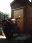
The second picture shows it installed (roughly)
A fork gaiter (for a Chinese pit bike £2.38 the pair) is to be run between the plate and what will be a CF infill panel on the right side of the steering head. All the wires passing round the steering head will be threaded through this fork gaiter. A 6 pole AMP connector just fits through. The connections from the main loom having passed through the gaiter will be approaching the swivel piece vertically from the top. When the steering is turned the loom will hopefully remain static except that the connector carrier will swivel taking about half the travel from the loom. I have hopefully allowed sufficient spare loom on the other side of the swivel piece so that the act of swivelling and the resultant lengthening of any cable runs downstream of the swivel piece can be accommodated within the space behind the fly-screen. The positioning of the swivel piece should prevent any part of the loom being trapped in the lock stops.
There is just enough clearance between the swivel piece and the headlamp shell, although this mark 1 prototype has been rigged up with 5 x 6 pole AMP connectors and the actual requirement dictated by the loom I have made is for 3 x 5 pole and 2 x 4 pole so I am reasonable confident the space is available. It is also mounted low enough to clear the instruments and the CCTV monitor.


350TSS is offline   Reply With Quote
Old 20-02-2018, 05:25 PM   #564
Albie
Fanactical volunteer
 
Albie's Avatar
 
Join Date: Oct 2003
Location: Kent
Bike: M900
Posts: 9,031
Steady progress. If I have time I'm working near you tomorrow and or Thursday try to pop in for a brew
Albie is offline   Reply With Quote
Old 20-02-2018, 05:54 PM   #565
350TSS
Too much time on my hands member
 
350TSS's Avatar
 
Join Date: Jan 2013
Location: Shipbourne
Bike: M900
Posts: 1,419
Albie,
Tomorrow I am out til about 12.00, then in garage until about 16.00
Thursday Ok from 09.15 til 16.00,
Either way text me and I will put kettle on
350TSS is offline   Reply With Quote
Old 20-02-2018, 07:20 PM   #566
350TSS
Too much time on my hands member
 
350TSS's Avatar
 
Join Date: Jan 2013
Location: Shipbourne
Bike: M900
Posts: 1,419
Whilst I have not been in the garage much I have still been working on the bike in my mind, planning stuff, looking critically at stuff already done etc – if you are not happy with the way something is turning out much better to sort it out now before it gets to painting stage.
For example, my mold for the CF enclosure, originally designed for the coils (but now housing the Ignitech unit). I made the mold as deep as possible to accommodate the coils long ways so about 100mm deep, coils are now to be located elsewhere just in front of the rear cylinder and just higher than the valve adjustment covers. An enclosure for the Ignitech box only needs to be 70mm deep.
This will permit about 30mm of extra air to the rear cylinder.
If I shorten the original CF mold then the under steering stem mounting for the regulator can fit behind the stem instead of in front of it, provided I use the shorter original regulator /rectifier rather than the MOSFET one.
I had been struggling to work out how to wire the MOSFET anyway and was not sure that a 2 wire alternator would ever work with it. An added bonus is that behind the steering stem is further away from the line of the forks and therefore the potential clash between regulator and front mudguard less likely. I do like my forks as low in the yokes as possible for quicker steering and the originally planned MOSFET position may have compromised this.
Also, if I angle the base of the mold I can attach the regulator to the bottom of it whilst retaining the bearing location at the bottom of the steering stem which would be much better than having the bracket as a forward facing cantilever. So, for not much extra work it is a win – win – win. Trouble is thinking like this means the project gets longer and longer, my estimated hours to complete is still 430
350TSS is offline   Reply With Quote
Old 21-02-2018, 05:11 PM   #567
350TSS
Too much time on my hands member
 
350TSS's Avatar
 
Join Date: Jan 2013
Location: Shipbourne
Bike: M900
Posts: 1,419
Today’s progress, a failure to find anything in the garage to wrap around larger diameter alternator cables where they go through the sealing gland in the alternator case. I know I have something suitable but just cannot remember where I put it.
A small success though with the 2 x alternator cable connectors made from 6mm hexagon brass bar, through drilled 2.5mm to take the cables and 4 x 2.5mm holes drilled on one flat of the hexagon and then tapped 3mm. 3mm x 3mm socket grub screws will clamp the cables to be joined (or separated). The connectors will be staggered, individually heat shrink wrapped and then shrink wrapped as a pair.
350TSS is offline   Reply With Quote
Old 21-02-2018, 06:41 PM   #568
Darren69
Transmaniacon MOC
 
Darren69's Avatar
 
Join Date: Sep 2013
Location: Sutton In Ashfield
Bike: Multiple Monsters
Posts: 6,023
Brass although an alloy of copper is only 28% as conductive as copper itself. So may not the best material to use.
__________________
Roast Beef Monster!

Termignoni and Bucci - Italian for pipe and slippers!

S4 Fogarty, S4R 07T, 748, Series 1 Mirage
Darren69 is offline   Reply With Quote
Old 21-02-2018, 07:19 PM   #569
350TSS
Too much time on my hands member
 
350TSS's Avatar
 
Join Date: Jan 2013
Location: Shipbourne
Bike: M900
Posts: 1,419
Point taken, on the other hand, copper is not very mechanically strong or good at taking/sustaining threads, secondly I do not know where I could buy copper bar and finally, most old style 13 amp plugs have solid brass pins and they work at 240v and up to 13 amps.
I think the brass will work OK and it is better than the bullet style flimsy connectors fitted as standard
350TSS is offline   Reply With Quote
Old 21-02-2018, 07:53 PM   #570
Darren69
Transmaniacon MOC
 
Darren69's Avatar
 
Join Date: Sep 2013
Location: Sutton In Ashfield
Bike: Multiple Monsters
Posts: 6,023
Yea I'm sure it will be fine. Maybe you could copper plate them?
__________________
Roast Beef Monster!

Termignoni and Bucci - Italian for pipe and slippers!

S4 Fogarty, S4R 07T, 748, Series 1 Mirage
Darren69 is offline   Reply With Quote
Reply


Posting Rules
You may not post new threads
You may not post replies
You may not post attachments
You may not edit your posts

BB code is On
Smilies are On
[IMG] code is On
HTML code is Off

Forum Jump


All times are GMT. The time now is 11:39 PM.

vBulletin Skins by vBmode.com. Powered by vBulletin® Version 3.8.3
Copyright ©2000 - 2024, Jelsoft Enterprises Ltd.