UK Monster Owners Club Forum » .: Technical :. » Mods & How To's » Slow Monster rebuild

Reply
 
Thread Tools Display Modes
Old 20-09-2018, 09:19 PM   #721
350TSS
Too much time on my hands member
 
350TSS's Avatar
 
Join Date: Jan 2013
Location: Shipbourne
Bike: M900
Posts: 1,419
Had a good day in garage today, knocked up a head bearing press arrangement from 8mm studding and some “washers” made by using a 54mm dia hole saw. Normally I would have no qualms about a block of soft wood and a lump hammer to get the outer races in but I am a bit nervous of spoiling the “chrome” powder coating. The outer races are not aligned properly in the picture below.


If I press the head races outers in tomorrow then this will be a bit of a milestone, the first thing that I have done that constitutes actual re-building. I mustn’t get too excited though as I have still got an estimated 330 hours to completion.
I gave the tank pattern about 2 hours of a (final?) rubbing down with 2000 and 4000 abrasive pads and got a satisfying polish to it.
I also spent some good thinking/ planning time, a) working out how and where to split the tank mould and b) how and where to mount the front anchor point for the rear brake torque arm. This point b) will have to be a bit of a compromise.
Originally I had intended to mount it directly to the crankcase in the rear most bottom through bolt hole (which was probably designed for a centre stand pivot and is not used on any of my Ducatis). Indeed I tapped the hole to take a bolt to attach the spherical bearing on the end of the torque arm. This would create potentially a clearance problem for the tyre as it is c25mm inboard of the inner edge of the swinging arm leg. Whilst this crankcase bolt hole is almost vertically below the swinging arm pivot, it is at 110mm from the SA centre line, the distance between the centre of the rear axle and the centre of the rear brake pads is 104mm.
I have pretty well worked out what the bracket will look like and am confident I can keep the torque arm as far as possible parallel with the SA through the full range of suspension movement whilst avoiding a clash with the tyre. It will probably take a few iterations of the bracket to get it right, but that is part of the fun.
Also I made excellent progress on the CF belt cover patterns but did not quite finish them - pictures to follow tomorrow.
350TSS is offline   Reply With Quote
Old 21-09-2018, 04:32 PM   #722
350TSS
Too much time on my hands member
 
350TSS's Avatar
 
Join Date: Jan 2013
Location: Shipbourne
Bike: M900
Posts: 1,419
Another solid day’s progress today, I started with the belt cover pattern bases and nearly finished them. The object was to get a smooth base that matched the steps in the original belt covers where they mate to the engine.
I needed about 5 sq feet of 12mm ply and did not quite have enough so offcuts were jig sawed together and glued onto a base, this took longer than anticipated as I had to wait for the evo stik to dry.
This was covered in 3mm polypropylene sheet which has excellent release properties which was also glued to the base, so more waiting
Whilst I was waiting I thought would try and progress the crankcase front torque arm bracket. I spent a long time measuring and checking all the critical dimensions, as best I could with the engine not attached to the frame and the swinging arm absent. I used 10mm aluminium plate and am pleased with the result. The 10mm bolt in the picture is the wrong thread (too coarse) but is just “engaged“ so as to prove that the holes were drilled in the right place. The hole for the bolt which will attach the spherical bearing on the outside of the plate has been tapped 8mm so that I can use either a lock nut or preferably drill the bolt and put an R clip through it on the inner side of the bracket.
I only hope neither the bracket nor the torque arm will not foul the exhaust pipe, one of the perils of working out of sequence, although I am pretty confident it will clear, fingers crossed.


The second picture shows the belt cover mould bases with the covers themselves having had a first application of filler, not yet rubbed down. In the background is the Mk4 brake hanger bracket with a slightly more curvaceous design. Unfortunately cutting curves in 10mm plate is not compatible with jig saw blade life and I had to stop for the day when my last metal blade broke.
350TSS is offline   Reply With Quote
Old 24-09-2018, 10:01 AM   #723
Dukedesmo
Registered User
 
Dukedesmo's Avatar
 
Join Date: Sep 2010
Location: Leics
Bike: M900
Posts: 2,842
Unless you've got some weirdly tucked in exhaust then the the rear brake torque arm bracket will easily clear it.

With the exhaust on the outside of the swingarm and the torque arm on the inside, there is loads of clearance, around 40-50mm on mine.
__________________
M900, 916, LeMans II.

Dukedesmo is offline   Reply With Quote
Old 28-09-2018, 10:57 PM   #724
350TSS
Too much time on my hands member
 
350TSS's Avatar
 
Join Date: Jan 2013
Location: Shipbourne
Bike: M900
Posts: 1,419
Good progress in the last couple of days, steering head bearings now in situ. My press did not work that well initially so an aluminium drift was used to get the outer bearings in about half way then pressed in the last bit.
The new bearings came with a pair of dust seals with a bonded on neoprene/rubber /viton lip seal for top and bottom which looked as if they would work well, but when I assembled it they were causing the steering to be too tight so it all had to come down again and just the original un-rubbered dust coverl was put back under the top stem nut.
The original rusty and pitted dust cover (seal is too strong a word for it) was treated to a wire brush in an electric drill, a hydrochloric acid bath (brick cleaner) and then given a zinc plating in my home brewed plant (15 minutes at 0.5 amps/12volts) and it came out rather well.


I also knocked up some aluminium nuts for the lock stops (saving more than the weight of one steel nut) but I am not sure which side of the cast lug on the bottom yoke they are supposed to go? I used 8mm x 30mm stainless grub screws for the lock stop “bolts” off ebay, (sorry Nasher).
I need to spacer the rear disc away 10mm from the wheel so I used a 25mm hole saw to create some spacers from the 10mm plate I have. The chances of me being able to turn 6 bushes on the lathe all the exact same thickness is very pretty remote so using this method at least I know the bushes are 10mm thick.


Lastly I turned down my solid 20mm titanium SA spindle. It was nowhere as near as bad to machine as the martensitic (?) stainless steel top hat bushes for the brake hanger. I could not find out what to use as cutting fluid so I used copious quantities of WD40 and probably did my lungs no good at all breathing the fumes as it vaporised when it touched the tip of the cutting tool.


The 10mm diameter spigot on the end of the SA spindle has a purpose which will be revealed in the next instalment.
I shall try to get the titanium spindle plated with the diamond hard carbon stuff when I have finished buggering about with the reason for the spigot.
350TSS is offline   Reply With Quote
Old 29-09-2018, 11:15 AM   #725
utopia
No turn left unstoned
 
utopia's Avatar
 
Join Date: Jun 2010
Location: leicester
Bike: M750
Posts: 4,545
QUOTE .. I could not find out what to use as cutting fluid so I used copious quantities of WD40 and probably did my lungs no good at all breathing the fumes as it vaporised when it touched the tip of the cutting tool.

I use Clarke cutting fluid from Machine Mart, applied using a kids paintbrush as my lathe has no pumped coolant system.
£8.39 for a 1 litre plastic bottle and it works really well for titanium.
For titanium, I would use a slow spindle speed and a fairly heavy feed, which also helps to keep the heat down.
I also avoid taking light skimming cuts as this tends to make the material work harden. It cuts much better if you give the tool a decent depth of cut to get its teeth into.

If you pm Capo, he can tell you where he got his ti swinger spindle "diamond" coated.
utopia is offline   Reply With Quote
Old 29-09-2018, 01:11 PM   #726
Capo
You Are What You Is
 
Join Date: May 2005
Location: A Foward Location
Bike: S4r
Posts: 1,948
Capo is offline   Reply With Quote
Old 29-09-2018, 01:15 PM   #727
Capo
You Are What You Is
 
Join Date: May 2005
Location: A Foward Location
Bike: S4r
Posts: 1,948

Last edited by Capo; 29-09-2018 at 01:17 PM..
Capo is offline   Reply With Quote
Old 29-09-2018, 01:22 PM   #728
Mossleymonster
Registered User
 
Mossleymonster's Avatar
 
Join Date: Nov 2017
Location: Barnsley
Bike: M1100s
Posts: 238
I know I'm going to need this as hopefully my bike is a keeper. Pray tell who dun it, and "OW MUCH" (Thats yorkshire)
__________________
Always remember. Your home is at risk if you set fire to it.
Mossleymonster is offline   Reply With Quote
Old 04-10-2018, 09:19 AM   #729
350TSS
Too much time on my hands member
 
350TSS's Avatar
 
Join Date: Jan 2013
Location: Shipbourne
Bike: M900
Posts: 1,419
I had an enjoyable day yesterday making a drive chain tensioner (not another hair- brained scheme I hear you say) and almost finishing the Mk4 brake hanger.
It is a long time since I rode this Monster but I do recall my first impression of quite a snatchy transmission at low speed. Some have gone down the 14T front sprocket route, others increase the number of teeth on the rear sprocket by two or three. Years ago I read an article written by a Yamaha engineer who said that a good minimum size for a sprocket was 19T, anything smaller and the chain wore faster because of the increased loads on the individual rollers and the transmission would snatch because of the chain being forced to follow a smaller radius at the front sprocket. As a general rule I notice that Yamahas seem to have larger rear sprockets than other makes so they seem to follow that philosophy.
Also if you have ever watched a bike on a dyno or seen you tube videos and see how much the chain oscillates when the bike is run up through the gears it is quite alarming.
We are obviously stuck with a 15T maximum by design.
The pivot point for the chain tensioner has to be the swinging arm spindle otherwise any suspension movement would alter the geometry and hence any tension applied to the chain. The purpose obviously of the tensioner is to smooth/dampen out the variations in chain tension caused by the combination of suspension movement and the swinging arm pivot being not concentric with the gearbox sprocket.
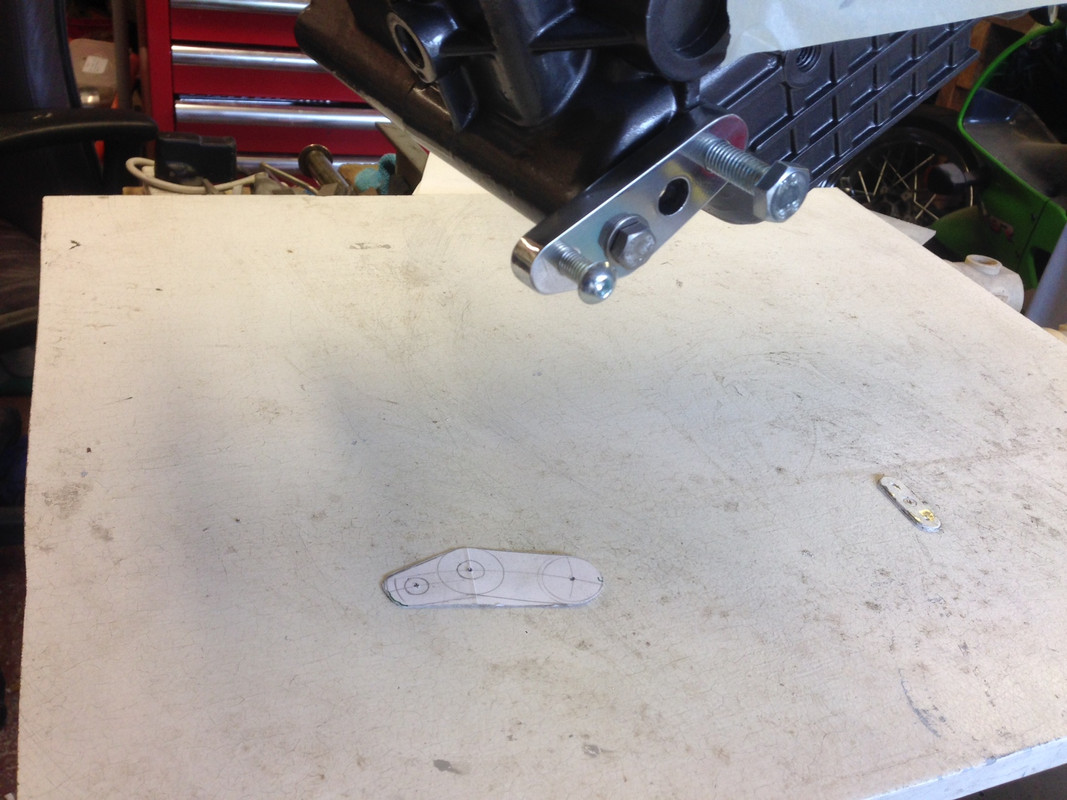
The first iteration of my chain tensioner design involved a 10mm spigot on the end of the swinging arm spindle with a 10mm ID x 22mm x 6mm ball race pressed into a 6mm aluminium plate carrying the chain tensioning roller.
If I had thought about it for a nano-second I would have realised that this was never going to work as any side loading would have very quickly separated the bearing from the plate.
The titanium spindle I turned up with the 10mm diameter spigot will now have the spigot removed and will be used on the 750SS rebuild. The Mk 2 titanium spindle will have a 17mm spigot 21mm long to take an inner sleeve 20mm OD for a needle roller bearing.
I decided to go with a 20mm ID x 26mm OD x 20mm long needle roller with integral seals. The original 22mm hole in the tensioner blade (I did not want to make another one) had to be accurately opened out to 26mm. Filing it produced a rough approximation of a 50p piece and I eventually settled for using a small drum sander on my Dremel and managed to get a round(ish) hole that was a good interference fit on the needle roller.
The needle roller needed a 14mm deep outboard housing which was duly turned up (twice because I over bored the first one (???) DOH!!!). I will secure this bearing housing to the tensioner plate with some 3mm stainless socket cap screws and probably locate the needle roller laterally with a 4mm grub screw.

screen capture software

At the chain end I got a roller off a cheap Chinese pit bike tensioner, fitted two 8mm x 22mm x 7mm sealed ball races inside in place of a plain bored steel tube.
A 6mm support plate was added to the inner roller end to support the roller bearing bolt and to keep the tensioner roller perpendicular to the rollers on the chain.
350TSS is offline   Reply With Quote
Old 04-10-2018, 09:23 AM   #730
350TSS
Too much time on my hands member
 
350TSS's Avatar
 
Join Date: Jan 2013
Location: Shipbourne
Bike: M900
Posts: 1,419
The tensioning “spring” will be 6mm diameter bungee cord clamped to the tensioner plate where the two 6mm bolts attach the support plate. The 6mm bungee cord will be looped round an aluminium “cotton reel” attached to the swinging arm where the standard nylon swinging arm/ chain protector is bolted on. I chose bungee cord because being rubber it has natural damping although exposed to the elements it might need changing fairly frequently. The clamp fixing should enable me to easily adjust the tension.
Obviously I do not know if it will work. I will let you all know sometime next year.
Today’s tasks are to a) make the bungee clamp arrangement on the tensioner blade; b) turn up the “cotton reel” for the upper from 25mm dia aluminium bar; c) get rid of all the filing marks and polish the plates; d) drill and tap the bearing support and attach it to the tensioner blade.
350TSS is offline   Reply With Quote
Old 04-10-2018, 10:46 PM   #731
350TSS
Too much time on my hands member
 
350TSS's Avatar
 
Join Date: Jan 2013
Location: Shipbourne
Bike: M900
Posts: 1,419
Chain tensioner all done today except I need a new 20mm titanium bar for the SA spindle (promised for tomorrow and some 3mm stainless socket cap screws due on Monday).


New rear disc arrived from China - £32 off flea bay it weighs around 40 grams more than the old one but not really surprising as that was at the lower thickness limit, does this mean I must now buy some titanium bolts? Although one has to be steel to activate the speedo sensor.
350TSS is offline   Reply With Quote
Old 04-10-2018, 10:49 PM   #732
350TSS
Too much time on my hands member
 
350TSS's Avatar
 
Join Date: Jan 2013
Location: Shipbourne
Bike: M900
Posts: 1,419
Sorry Chain tensioner picture should have been this one
350TSS is offline   Reply With Quote
Old 04-10-2018, 10:53 PM   #733
350TSS
Too much time on my hands member
 
350TSS's Avatar
 
Join Date: Jan 2013
Location: Shipbourne
Bike: M900
Posts: 1,419
The bungee clamp was made with a scrap piece of 6mm plate cross drilled slightly off centre at 4mm and the cut through with a hack saw and opened out with a conical grindstone in the Dremel. The bungee at rest is 5mm diameter so is clamped nicely in a 4mm diameter half moon.
350TSS is offline   Reply With Quote
Old 08-10-2018, 08:54 PM   #734
350TSS
Too much time on my hands member
 
350TSS's Avatar
 
Join Date: Jan 2013
Location: Shipbourne
Bike: M900
Posts: 1,419
Slightly frustrating day, I wanted to thread up some 10mm titanium bar to replace the two long engine bolts. Some while ago I bought (on advice from Nasher I think) a tail-stock die holder. This was my first opportunity to use it. I comes with 2 sizes of die holder both too big for the 10mm die that I have which is 25mm diameter.
I thought about turning up some aluminium bar but remembering the struggle I had before with running the die down some 8 mm titanium bar I quickly rejected that idea. So I spent a long time scouting round for a bit of steel 38mm diameter to fit in one of the supplied die holders. I had the martensitic steel bar but could not face machining that.
I did find a steel collar bored 25mm and 40mm outside diameter but it was only 16mm long and I need at least 13mm so I had to work out how to hold it in the lathe.
In the end I drilled and tapped the collar and with a 6mm grub screw attached it to about 75mm of 25mm diameter aluminium bar which went nicely in the 3 jaw chuck.
The threading went OK after I machined a 5mm lead in on the 10mm bar but it was hard work requiring two x 18 levers, one to lock the lathe 3 jaw chuck and another on the die holder.

Result though is two engine bolts in titanium saving 125g on the steel items. I also got left with a 50mm length of 10mm titanium which I will thread to make the crankcase rear brake hanger reaction rod fastening.
post a picture
350TSS is offline   Reply With Quote
Old 09-10-2018, 07:18 AM   #735
Darkness
.
 
Darkness's Avatar
 
Join Date: May 2007
Location: Stockbridge
Bike: M900
Posts: 1,984
Interesting post (As always) Richard, but on mine one of the engine bolts threads into the frame itself rather than having a nut at the end. Is yours the same?
If you replace the bolt with a length of bar threaded at both ends, you can easily fit it by winding a nut on till it goes tight, then screwing it in place, but how do you ensure you can get it out again: if the nut comes off first you’ve nothing to turn the bar with?
Just worrying for you!
__________________
Original and Best since 1993
Darkness is offline   Reply With Quote
Reply


Posting Rules
You may not post new threads
You may not post replies
You may not post attachments
You may not edit your posts

BB code is On
Smilies are On
[IMG] code is On
HTML code is Off

Forum Jump


All times are GMT. The time now is 11:39 PM.

vBulletin Skins by vBmode.com. Powered by vBulletin® Version 3.8.3
Copyright ©2000 - 2024, Jelsoft Enterprises Ltd.