As I mentioned in my other thread about my broken gearchange return spring...
http://www.ukmonster.co.uk/monster/s...d.php?p=567800
As well as access to the gear change mechanism, the alternator cover also has to be removed to get to the alternator (obviously!), or if you want to change the flywheel or remove the starter motor. So I thought I'd post up a step-by-step guide to removing the cover, which someone might find useful in future.
You will need...
The following hex bits:
4mm
5mm
8mm socket (for sidestand switch).
Silicone gasket remover and/or suitable scraper.
Threebond 1215 (Loctite equivalent 5910)
Oil drain pan.
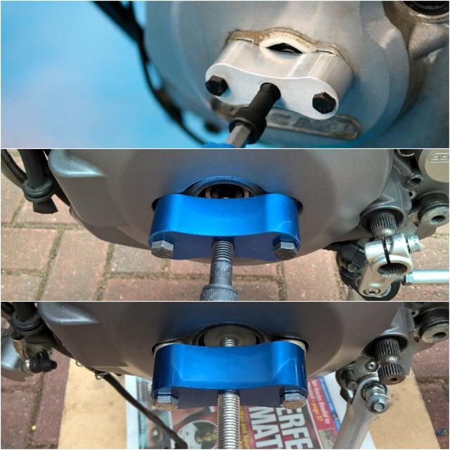
Alternator cover puller. Note - if you use a Laser 5334 on a later model Monster like the 696/796/1100 you will need to modify it slightly. The old Monster's inspection cover sat on a machined surface that was proud of the alternator cover, while the newer Monsters have the machined surfaces recessed below the surface.

So, if you try to use the Laser tool on the newer cover, it will sit on the painted surface and the screws will be too short. To adapt it, I've added a couple of 12mm x Ø15mm spacers so the tool now sits on the machined surface and is clear of the paint. I've also used longer M6 mounting screws (40mm) and M10 centre screw (70mm).
Here's a comparison showing the tool on an old-style cover, then on my 1100 (bearing on the painted surface) and finally with spacers and longer screws.
Since the alternator runs in oil, before you pop the cover you'll need to drain the oil (M12 - 20Nm). Alternatively, if you can do it safely, leaning the bike to the right by 20° or so will allow you to remove the cover without draining the oil.
Disconnect the gear change mechanism from the shaft (1 x M6 - 10Nm) after marking the correct position of the arm. Clean up the splines to help protect the seal, especially if you're not planning to change it.
Remove the sidestand switch (1 x M6 - 5Nm + threadlock).
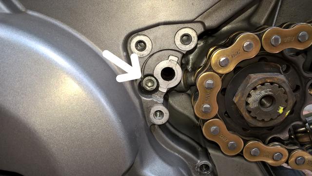
Remove the sprocket cover (2 x M6 - 6Nm) and clutch slave (3 x M6 - 10Nm) and withdraw the clutch pushrod. Be careful to retain the anti-rotation pin as it can easily fall out. Take the opportunity to clean out any chain lube gunge and locate the infamous 'hidden' screw (arrowed).
Remove the front cable guide (2 x M5 - 5Nm) noting the location of the special screws.


 Threaded Mode