UK Monster Owners Club Forum » .: Technical :. » Mods & How To's » Slow Monster rebuild

Reply
 
Thread Tools Display Modes
Old 20-01-2021, 05:25 PM   #1306
350TSS
Too much time on my hands member
 
350TSS's Avatar
 
Join Date: Jan 2013
Location: Shipbourne
Bike: M900
Posts: 1,419
I have had a productive couple of weeks knocking some of the jobs off the list. Inevitably a few new ones emerged as I laboured on
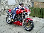
The tank got new larger "Ducati" stickers which were lacquered in and subsequently polished. The finish on all the paintwork is good for a rattle can job but what I would call a "2 metre finish" - looks Ok from 2 metres but closer examination shows the flaws in the underlying CF and in the paint finish itself.
A new top mount for the flyscreen was fabricated based on 2 aluminium prongs projecting forward from the top of the instrument mount which fitted inside two 30mm deep cups fitted to the end of a rubber vibration mount. the cup and the prong were cross drilled to take a 3mm R clip. I am quite pleased with the outcome, the tank / seat and flyscreen can be removed in less than a minute with just the use of a 3mm allen key to undo the seat latch - no other tools required.
I finally got the monitor to talk to the camera. the monitor had 2 x coax leads and one power lead jack plugs coloured white and yellow and red respectively. the connection to the camera had similar leads. Stupidly I assumed that the yellow should go to the yellow and the white to the white, when I switched them the camera and monitor worked as if by magic. The rear view is actually pretty good via the monitor although we will obviously have to see how it copes with vibration and suspension movement.
Still struggling with the left hand switch and the loss of correlation between the switch position and which lights are illuminated. I seem to have gained working main beam but only for about 2 seconds then it switches itself off. I also have a new problem in that the sidelights stay on after I have switched off the ignition but extinguish if I turn it on and off again at the ignition. I shall give it one more day of messing with before I have to bite the bullet and buy one those expensive sequential pushbutton switches and rewire the left hand handlebar switch.
Aside from the LH switch only a few more jobs to do now, - bleed the rear brake, fit the petrol tap and connect the pipes to the vacuum pump, get the ignition system to deliver a spark (could be a number of issues here - coils wired the wrong way round, air gap for the magnets to the Hall effect sensors or incorrect/faulty wiring to the Ignitech unit).
Some piccies
tony colgan


Last edited by 350TSS; 20-01-2021 at 05:28 PM..
350TSS is offline   Reply With Quote
Old 20-01-2021, 05:30 PM   #1307
Darkness
.
 
Darkness's Avatar
 
Join Date: May 2007
Location: Stockbridge
Bike: M900
Posts: 1,984
Silly question, but is the rear view image reversed so that objects on the offside of the bike are on the right, like you’d see in a mirror, rather than having them on the left, as you’d have if you looked over your shoulder?
__________________
Original and Best since 1993
Darkness is offline   Reply With Quote
Old 20-01-2021, 05:39 PM   #1308
350TSS
Too much time on my hands member
 
350TSS's Avatar
 
Join Date: Jan 2013
Location: Shipbourne
Bike: M900
Posts: 1,419
No the image is as if you turned round to look at it.
350TSS is offline   Reply With Quote
Old 20-01-2021, 05:43 PM   #1309
350TSS
Too much time on my hands member
 
350TSS's Avatar
 
Join Date: Jan 2013
Location: Shipbourne
Bike: M900
Posts: 1,419
It was not a silly question as I posted the last reply I had to have another think about it before I concluded that my response was correct
350TSS is offline   Reply With Quote
Old 20-01-2021, 06:04 PM   #1310
slob
.
 
slob's Avatar
 
Join Date: Jul 2003
Location: East London
Bike: Multiple Monsters
Posts: 9,710
but since the camera is facing in the same direction as the screen, surely what’s on your left is still in the left of the screen?
slob is offline   Reply With Quote
Old 20-01-2021, 06:16 PM   #1311
Darkness
.
 
Darkness's Avatar
 
Join Date: May 2007
Location: Stockbridge
Bike: M900
Posts: 1,984
Quote:
Originally Posted by slob View Post
but since the camera is facing in the same direction as the screen, surely what’s on your left is still in the left of the screen?
You sure about that Rob? A viewfinder is usually on the back of a camera, not facing the same way as the lens.
__________________
Original and Best since 1993
Darkness is offline   Reply With Quote
Old 20-01-2021, 06:22 PM   #1312
350TSS
Too much time on my hands member
 
350TSS's Avatar
 
Join Date: Jan 2013
Location: Shipbourne
Bike: M900
Posts: 1,419
Stting on the bike if I look over my left shoulder I should see a ZX9R exiting to my left (reality) the monitor shows exactly that
350TSS is offline   Reply With Quote
Old 20-01-2021, 06:30 PM   #1313
slob
.
 
slob's Avatar
 
Join Date: Jul 2003
Location: East London
Bike: Multiple Monsters
Posts: 9,710
Quote:
Originally Posted by Darkness View Post
You sure about that Rob? A viewfinder is usually on the back of a camera, not facing the same way as the lens.
okay then. get your phone and take a selfie with your eg. left eye shut.
now using the regular camera, turn the phone round and take another photo with the same eye shut.
compare the photos, both show your left eye shut but it’s on the right of the photo. the reversal is something of an illusion...
slob is offline   Reply With Quote
Old 20-01-2021, 09:03 PM   #1314
manwithredbike
aka Phil
 
manwithredbike's Avatar
 
Join Date: Nov 2005
Location: derry
Bike: M900
Posts: 376
Rear view camera images are reversed to simulate what a rear view mirror shows you.
__________________
..
~
manwithredbike is offline   Reply With Quote
Old 20-01-2021, 10:03 PM   #1315
Darkness
.
 
Darkness's Avatar
 
Join Date: May 2007
Location: Stockbridge
Bike: M900
Posts: 1,984
Quote:
Originally Posted by manwithredbike View Post
Rear view camera images are reversed to simulate what a rear view mirror shows you.
Yip, that’s what I thought.
__________________
Original and Best since 1993
Darkness is offline   Reply With Quote
Old 21-01-2021, 07:40 AM   #1316
Nasher
Registered User
 
Nasher's Avatar
 
Join Date: Jul 2014
Location: Portsmouth
Bike: M900
Posts: 1,510
Quote:
Originally Posted by manwithredbike View Post
Rear view camera images are reversed to simulate what a rear view mirror shows you.
Yes, I'd agree with that.
It's certainly that way in my car, and wouldn't work any other way to use when reversing.
Not that you'll be reversing the bike with it, but I think I'd get confused if it wasn't reversed.

Nasher.
__________________
Heaven doesn't want me, and Hell is afraid I'll take over.
Nasher is offline   Reply With Quote
Old 21-01-2021, 08:57 AM   #1317
slob
.
 
slob's Avatar
 
Join Date: Jul 2003
Location: East London
Bike: Multiple Monsters
Posts: 9,710
yup my mistake, my head hurts, the mirror illusion is something else
slob is offline   Reply With Quote
Old 22-07-2021, 02:39 PM   #1318
350TSS
Too much time on my hands member
 
350TSS's Avatar
 
Join Date: Jan 2013
Location: Shipbourne
Bike: M900
Posts: 1,419
Over the last 5 or 6 months, I have continued to worry the electrics on the Monster, not enough to make them work, but various modifications have been made, none of which resulted in an MOT passable lighting system.
I have come to the conclusion that the problem is the M unit, which is/was defective from delivery, or something I have done over the last 18 months has caused it to go defective. (not entirely impossible because I dropped a 10m deep socket which shorted the battery to the starter solenoid and caused a big flash).
The M unit is supposed to be a) a digital fuse box, b) a relay for every power circuit, c) a flasher can, d) a 16-way connection box, and seems to perform all the desired functions except 1 (enabling the main beam to stay illuminated for longer than 4 seconds).
The unit is fed from a 25 amp fuse between it and the battery via a 6mm cable to an insulated post on one end. The case of the unit is earthed. There are 16 screw terminals, 8 on each side - on the left side they connect to the controlling switch which switches to earth, and on the right-hand side the wires connect to the various components which are then earthed when the component does what it is supposed to.
Yesterday I made a brave decision, given the time I have invested in making the system work, I will scrap the M unit and rewire each circuit.
I do not understand relays or how to wire them so there will be no relays in the circuit. My reasoning for this is that with LED lights throughout there are no circuits that require a heavy current draw (with the exception possibly of the starter motor which has a solenoid to do the heavy lifting and is a mechanical relay anyway and possibly the horn which is a momentary action switch that will only get used once a year at MOT time).
The circuit diagram will be as simple as I can make it. Battery through the ignition switch to a busbar. From the busbar to a fuse box with a fuse for each of the horn, indicators, brake lights, ignition, dip, and main beam with an auxiliary power feed for the neutral light, voltmeter, daylight running lights, rearview camera, and monitor.
All the switches will be inline between the fuse box and the component that the switch controls and the earth will be individual to each component.
Whilst I shall not be starting from scratch the change in configuration and placement of the switches within the architecture of each circuit will effectively be a 60% rewire job.
I have the fuse box and the busbar on order and there could be space constraints as the M unit is very compact and I will have to locate the busbar/fuse box in the same space, currently occupied by the M unit. Nobody said it would be easy.
However, having made the decision I can look forward with optimism and enthusiasm for the project as frankly over the last few months I have not looked forward to working on the bike as I continued to bash my head against a brick wall, not really knowing what I had to do to fix it and going over similar ground with little hope of success.
The bits should arrive just before we go on holiday to Pembroke, so major effort during the remains of August and I may even get out on it this summer.

Last edited by 350TSS; 22-07-2021 at 02:43 PM..
350TSS is offline   Reply With Quote
Old 25-08-2021, 01:53 PM   #1319
350TSS
Too much time on my hands member
 
350TSS's Avatar
 
Join Date: Jan 2013
Location: Shipbourne
Bike: M900
Posts: 1,419
Help required
I have finally completed the 4th iteration of wiring this project and following the removal of the M unit I now have lights (DRL, instruments, indicators (including repeaters in the instruments) dip, and main beam, rear and number plate lights, brake lights) that should pass MOT, together with a working horn, working starter and run/kill switch. The camera and monitor works as does the voltmeter.
I have 3 remaining problems
1. The oil pressure switch remains a challenge. It effectively is an OFF switch which goes to earth through the clutch casing. When connected it blows the fuse, unsurprisingly as the single lead powering it is fed from the switched circuit from the ignition. I really want a double pole insulated oil pressure switch so that I can run power to it and the switch works when the oil pressure is OK and switches off the light on the instrument panel. I have spent some time searching the internet but cannot find one with 2 poles. I considered adapting a brake hydraulic switch and even obtaining a small pressure gauge and mounting it down on the clutch casing. It is not vital so a solution will emerge - I am currently favouring the gauge idea as it gives better information than a light which is not on when a preset minimum pressure is at the base of the switch.
2. The neutral switch does not light the indicator in the instruments at the moment - also not vital
3. The real reason for this request for help is that I have power to the coils (both sides) but no spark whatsoever.
The equipment fitted to the bike is as follows:
a) FastBike gear ignition Hall effect trigger mounted on the jack shaft drive belt pulley connected to
b) An Ignitech unit which came with the FastBike Gear and a wiring diagram that showed where the 9 or so wires going in and out of the unit should go on the possible 23 wiring positions available on the unit. It is definitely wired as FastBike gear recommend.
c) 2 x California Cycle works high output coils. With the ignition turned on and the kill switch in the "run" position I have 12 volts on both terminals on each coil. I have tried reversing the coil connections and in either orientation there are no sparks when the starter motor is cranked.
The starter motor spins the engine faster (with the spark plugs in) than I have ever heard any Ducati starter motor. The plugs are new NGK, not iridium. The leads are new, the caps are new, NGK, supplied with the coils so I am assuming there are no issues with whether or not the caps are fitted with resistors or not.

There are no exciter units and I am wondering if the system would need something to amplify the signal from the Hall effect unit or whether the Ignitech unit performs that function?

All suggestions gratefully received
350TSS is offline   Reply With Quote
Old 27-08-2021, 09:41 AM   #1320
hh93
Member
 
Join Date: Jul 2018
Location: Lincoln
Bike: M620ie
Posts: 116
Quote:
Originally Posted by 350TSS View Post
Help required

1. The oil pressure switch remains a challenge. It effectively is an OFF switch which goes to earth through the clutch casing. When connected it blows the fuse, unsurprisingly as the single lead powering it is fed from the switched circuit from the ignition. I really want a double pole insulated oil pressure switch so that I can run power to it and the switch works when the oil pressure is OK and switches off the light on the instrument panel. I have spent some time searching the internet but cannot find one with 2 poles. I considered adapting a brake hydraulic switch and even obtaining a small pressure gauge and mounting it down on the clutch casing. It is not vital so a solution will emerge - I am currently favouring the gauge idea as it gives better information than a light which is not on when a preset minimum pressure is at the base of the switch.

All suggestions gratefully received
Try wiring up the Oil light another way:

Power to the bulb
earth from the bulb to the P Switch.

With power on the bulb should be lit. Once there is oil pressure the switch unmakes breaking the circuit putting the light out.

Similar with the Neutral Light

regards
Howie
__________________
Doris '03 620 Dark
Horace 1980 onwards Harris Mag II
hh93 is offline   Reply With Quote
Reply


Posting Rules
You may not post new threads
You may not post replies
You may not post attachments
You may not edit your posts

BB code is On
Smilies are On
[IMG] code is On
HTML code is Off

Forum Jump


All times are GMT. The time now is 04:19 PM.

vBulletin Skins by vBmode.com. Powered by vBulletin® Version 3.8.3
Copyright ©2000 - 2024, Jelsoft Enterprises Ltd.