UK Monster Owners Club Forum » .: Technical :. » Mods & How To's » Slow Monster rebuild

Reply
 
Thread Tools Display Modes
Old 13-04-2020, 07:06 PM   #1201
350TSS
Too much time on my hands member
 
350TSS's Avatar
 
Join Date: Jan 2013
Location: Shipbourne
Bike: M900
Posts: 1,419
This last week I have still been feeling a bit odd and sleeping about 14 hours a day and when I did get into the garage I have been skirting around getting really stuck into the wiring. There were 2 reasons for this, the first was that I had to think of a way of getting the loom around the headstock and could not work out a design I was happy with and the second was that I am fairly sure I will have to cut off the AMP connectors and fit more conventional bullet connectors because of space considerations. My reluctance had quite a bit to do with the length of time it took to put them on in the first place.
Some may find my determination to find a solution to getting around the headstock with the loom a bit obsessional, but I have owned four bikes where I suffered from intermittent wiring issues (XBR Honda, Honda Bros, KZ400 and ZX9R Kwaks) and it is a right PITA when it strikes.
Below is a picture of the Mk 2 and Mk 3 versions of my solution.
The Mk2 on the right, now discarded, relied on a carrier for the AMP connectors which swivelled when the steering was turned.
The Mk 3 is bolted to the underside of the top yoke through the RH handlebar clamp threaded holes and consists of a 6 mm aluminium plate through which 2 x 6 mm csk socket screws are attached to two 20 mm diameter bushes through drilled and tapped 6 mm.
2 x 8 mm titanium spindles are turned down at each end to 6 mm and threaded at each end with a plain space for 4 x 17 mm x 6 mm x 6 mm sealed ball races. The rollers are 19 mm plastic electrical conduit bored at each end to accept the ball races.
A 6 mm aluminium plate at the bottom holds the rollers in line.
The wiring loom(s) will pass between the rollers which will turn with the steering.

Last edited by 350TSS; 14-04-2020 at 02:08 AM.. Reason: correction
350TSS is offline   Reply With Quote
Old 14-04-2020, 12:04 AM   #1202
manwithredbike
aka Phil
 
manwithredbike's Avatar
 
Join Date: Nov 2005
Location: derry
Bike: M900
Posts: 376
A very elaborate setup there and looks really well made. Have you considered using extra length and simply putting a helix or loop into the loom at the headstock area to 'absorb' the movement?
__________________
..
~
manwithredbike is offline   Reply With Quote
Old 14-04-2020, 02:17 AM   #1203
350TSS
Too much time on my hands member
 
350TSS's Avatar
 
Join Date: Jan 2013
Location: Shipbourne
Bike: M900
Posts: 1,419
Manwithredbike: Yes I have considered a loop/spiral but this has two problems;
1. space for it and where it would sit - ideally it would have to be centred on the tangent between the frame exit point for the loom and the headstock so at about 2.00 0'clock in plan view above the headstock. I have 20 + wires 1mm OD going around that corner, instrument nacelle, speedo sensor, LH and RH switchgear and front brake light switch, CCTV screen, headlamp and front indicators.
2. when I made the loom up I bought thin wall insulation cabling which actually seems to have stiffer composition insulation, added to the fact that in selecting the wire core size to use for each circuit I have chosen conservatively, probably using larger copper content than was strictly necessary for that particular circuit. Some might argue it is a problem of my own making.
350TSS is offline   Reply With Quote
Old 20-04-2020, 07:19 PM   #1204
350TSS
Too much time on my hands member
 
350TSS's Avatar
 
Join Date: Jan 2013
Location: Shipbourne
Bike: M900
Posts: 1,419
After a week of sleeping a lot, I finally managed to get into the garage today and made some progress.
I fitted my rollers and some rubber edging to the infill panel on the frame and after a bit of fiddling and trimming got the battery tray to sit right with the frame and the wiring.
4 lengths of bicycle inner tube protect the looms as they pass through the infill panel and around the rollers and I managed to hang the excess loom from 2 large rubber "O" rings suspended from nylon "P" clips attached to the instrument mounting studs.
I had to lose my re-settable 25 amp main fuse as there just was not enough room for it, I am now waiting for a waterproof 25 amp fuse holder to go between the battery and the positive side of the MU unit.
I managed to confirm that my starter solenoid fires (clicks) OK and confirm that it does not matter which orientation the input leads are connected, just as well as I forgot to make a note of the wiring and colours to it.


350TSS is offline   Reply With Quote
Old 22-04-2020, 12:34 AM   #1205
350TSS
Too much time on my hands member
 
350TSS's Avatar
 
Join Date: Jan 2013
Location: Shipbourne
Bike: M900
Posts: 1,419
I had a good 6 hours in the garage today playing with the wiring and I think I turned a corner today. Basically I had two problems, 1. where to put stuff so that I could run wires to it and have a reasonably tidy end product, that would be reliable and maintainable and 2. what wires go where.
Both are problems of my own making, 1. trying to cram too much equipment into too little real estate and 2 not finishing all the wiring when I first started it 6 months ago and not documenting accurately what I had done. The wiring diagram I obtained from Luddite was great but I did not have all the various colours in my box of wires so I made red-green wires by periodically putting green heat shrink on a red wire. But this did not always work as the colours of heat shrink are few and when I made them up I did not label them.
The first job today was to ensure that I could mount the MU unit securely as 18 wires go into this and sorting out the knitting behind the headstock and above the battery will require this unit to be securely mounted.
After about an hour of messing about, I realised that as long as I have a hole in my backside then it was never going to fit where I originally intended. I thought about a mezzanine platform above the battery but that would have interfered with the foam pod filters, angling it at 45 degrees below the ignition switch, but this would have required a new bracket, turning it through 90 degrees and raising it level with the base of the ignition switch was just the wrong orientation for the cable routes.

I settled in the end for making two 35 mm stands off the existing bracket which perversely means the unit takes up more of the available space but it does allow the 18 wires to get in and out of the unit securely without hindrance from side panels etc.

This meant the Ignitech enclosure had to be modified to get the new assembly in place. Unfortunately, I dropped it on the concrete floor which did nothing for the surface finish (why does the shiny side always land face down?) so it had to have a rub down and another coat of mat black.

I originally envisaged that all the earth wires would collect at one point and be bolted to the lug that secures the horn, also I made the earth leads from the battery, the regulator and the MU unit from HD welding cable, whilst very flexible they were taking up a lot of room.

The lithium battery I have chosen has two positive and two negative terminals, what I plan to do now is on the earth side to thread a stud directly onto one of the battery terminals, and all of the minor earth leads can be stacked directly onto that terminal. E.g. Stud threaded into captive nut on the battery terminal, locknut secures stud in the vertical position, earth lead 1, locknut, earth lead 2, locknut and so on.

With a bit more lateral thinking, putting the battery in the other way round reduced the route miles of the major earth leads, thereby reducing congestion in that area significantly.
As a consequence all the major earth leads needed to be re-made to different lengths.

The last hour was spent tracing the wires already in place but which I could not identify their purpose or intended destination. Needless to say, when identified they were labelled.

There is still some mileage /time to be invested before I get this bit done but at least now I have a way forward and whilst it will probably never be pretty it should look a lot less like a rat's nest.
Photos to follow when it looks half decent.
350TSS is offline   Reply With Quote
Old 23-04-2020, 07:23 PM   #1206
350TSS
Too much time on my hands member
 
350TSS's Avatar
 
Join Date: Jan 2013
Location: Shipbourne
Bike: M900
Posts: 1,419
A productive day today, first I managed to find a spring that very nearly worked as a brake return spring, it now does but I had to machine the bush it sits around down about 1 mm then I had to bend re-set the spring so the resting position was c 250 degrees between the "ears" (from about 160 degrees). I used my little cooking blow torch for creme brulee and locally heated to red heat then 2 pairs of pliers got the rough shape later finessed over a suitably sized arbour and a 1lb hammer.
I wondered about re- tempering the spring but could not remember if it should be heated and quenched in oil or just left to cool naturally. It seems OK so I just painted it with "chrome" paint.


Next, I mounted the MU unit and tidied the wires to and from it. There is still a bunch of knitting to sort out to the right of the unit.


Then I made up my earth stud but it looked very untidy so I found a lump of brass and made an earth bridge/block between the negative terminals. Its a bit heavy and in a couple of places the centre punching/drilling was a bit wayward but I think with a bit more work it should work fine.


Finally, I fixed something that has been bugging me - odd rubbers on the handlebar grips. At first, I thought I would just buy some new ones, then I saw the price. I actually bought some cricket bat handlebar rubber for £2, not only was it cheap, it has excellent grip qualities and also by rolling it over the original rubbers it makes the grip about 5 mm larger in diameter and more cushioned - result.

Last edited by 350TSS; 23-04-2020 at 10:59 PM.. Reason: wrong picture
350TSS is offline   Reply With Quote
Old 23-04-2020, 11:24 PM   #1207
350TSS
Too much time on my hands member
 
350TSS's Avatar
 
Join Date: Jan 2013
Location: Shipbourne
Bike: M900
Posts: 1,419
Just re-visited my ETTC. it is now down beneath 70 hours of which the painting of the tank, seat and fly-screen accounts for 24 hours, finishing the electrics is estimated at 23 hours, assembly is 19 hours including an allowance of 5 hours to upholster the seat.
There are only 2 more bits of fabrication, machining, drilling and tapping the reaction rod for the floating rear brake caliper and making some mesh grills for the 4 air scoops.
The remainder is stuff like bleeding the clutch and the brakes, buying and fitting new number plate, flushing out the oil cooler etc.
When this lockdown finishes I might just have a bike to ride.
350TSS is offline   Reply With Quote
Old 24-04-2020, 08:31 AM   #1208
manwithredbike
aka Phil
 
manwithredbike's Avatar
 
Join Date: Nov 2005
Location: derry
Bike: M900
Posts: 376
Quote:
Originally Posted by 350TSS View Post
Just re-visited my ETTC. it is now down beneath 70 hours of which the painting of the tank, seat and fly-screen accounts for 24 hours, finishing the electrics is estimated at 23 hours, assembly is 19 hours including an allowance of 5 hours to upholster the seat.
There are only 2 more bits of fabrication, machining, drilling and tapping the reaction rod for the floating rear brake caliper and making some mesh grills for the 4 air scoops.
The remainder is stuff like bleeding the clutch and the brakes, buying and fitting new number plate, flushing out the oil cooler etc.
When this lockdown finishes I might just have a bike to ride.
It'll be a bit weird seeing pics of a whole monster after 3 years of pics of bits and pieces!
__________________
..
~
manwithredbike is offline   Reply With Quote
Old 24-04-2020, 05:53 PM   #1209
350TSS
Too much time on my hands member
 
350TSS's Avatar
 
Join Date: Jan 2013
Location: Shipbourne
Bike: M900
Posts: 1,419
More bits and pieces today I'm afraid.
I spent a couple of hours re-making the earth block as the other one looked shonky and it was too heavy. No point spending loadsamoney on fancy wheels and titanium bolts if I use a boat anchor for an earth connector.
The Mk 2 came out better although a long way from perfect and a re-design reduced the weight from 50g to 30g.
bnb bank account details
I managed to connect 5 of the 7 leads to it but need to leave the last 2 until the bike is off the platform so I can test what happens to those leads when the handlebars are turned. On my platform, the front wheel is clamped straight ahead.
I jury-rigged the rearview camera and worryingly although the camera initially showed signs of life the monitor either had no signal or just does not work or my jury-rigging was faulty, a problem for another day.
350TSS is offline   Reply With Quote
Old 26-04-2020, 09:45 AM   #1210
350TSS
Too much time on my hands member
 
350TSS's Avatar
 
Join Date: Jan 2013
Location: Shipbourne
Bike: M900
Posts: 1,419
Very frustrating day today, minor steps forward and a couple backwards.
I spent the first hour trying to find out what a blue wire with intermittent yellow heat shrink does.
I checked the wiring diagram and all the notes I took when the loom was on the jig. No mention anywhere of a blue and yellow. I even powered it up to see if anything lit up - nothing.
In attempting to power it up, I thought I had better switch on the ignition, the key would go in and it would turn anti-clockwise, the steering lock bolt started to emerge. the barrel would depress satisfactorily but it would not turn clockwise to the ON position and power up the circuits.
Please tell me how a switch that has been sitting completely unmolested in an airtight, waterproof plastic box for 3 years which worked perfectly well before incarceration can fail the first time you want to use it?
I spent half an hour dousing the switch with WD40 and eventually, it just turned on.
It was quite exciting to see the dash light up for the first time but as to the blue and yellow wire, I am still none the wiser.
I thought I had better move onto something where I could actually make progress i.e mechanical not electrical.


.
350TSS is offline   Reply With Quote
Old 26-04-2020, 09:46 AM   #1211
350TSS
Too much time on my hands member
 
350TSS's Avatar
 
Join Date: Jan 2013
Location: Shipbourne
Bike: M900
Posts: 1,419
To do that the bike has to come off the engine stand, which meant removing the oil cooler. I rather foolishly sandblasted this before painting it and, although I sealed every orifice, when I first fitted it, I noticed some grittiness in the threads. I connected it to the hosepipe and turned it full on and left it watering the garden for half an hour. I think if there is any remaining grit inside it will probably stay there as mains pressure is surely a bit higher than a Ducati oil pump pressure. A blow through with compressed air and it was parked on a radiator overnight to dry out.
I thought I would get the LH side done first as that is the side of the bike my chair sits, fit the alternator cover end plate, my chain saver and sprocket cover then the gear lever and the side stand. LH side then finished.
I spent an hour looking or the alternator cover endplate. I have at least two of them, one original (damaged) and one given to me by Albie (modified) I cannot find either of them.
Moving to the case saver and the sprocket cover, I kind of knew this was going to be a bit of a struggle as the case saver has a certain springiness that has to be compressed slightly to align the bolt holes and avoid hitting the chain. The exertion of the necessary pressure through the sprocket cover is decidedly tricky. After about half an hour of buggering about I tried without the case saver in place. The CF cover I bought would not fit on its own, the bolt holes were 0.5mm misaligned and the cover clashed with the clutch slave cylinder. With these deficiencies Dremeled out of existence, it fell on with the case saver.
The gear lever was another pain. the rod connecting the pedal to the little clamp on the gear lever shaft has a RH thread in both ends, so adjusting the rod requires removal of one of the spherical bearings and guessing the length and re-assembling. To get the right mechanical advantage the clamp on the gear lever shaft needs to be as close to a right angle to the rod as possible. With it in that position and the spherical bearing adjusted out as much as I dare, the gear lever pedal is about 25 mm too high so I need to make a new longer rod (to do this properly would obviously mean buying a LH tap, a LH spherical bearing and a LH nut).
I fitted the side stand and, because of the higher, more tucked-in footrests, it looks awful, like a tanker aircraft trailing its refuelling hose, other than painting it black so it is less noticeable I am not sure what to do about it. I could not find the 12mm bolt that holds the stand to its post.
The final kick in the teeth for the day was that when I tried to spin the back wheel (I could not whist on the engine stand as the wheel rested on the floor) it is obvious that my hugger rubs the tyre so badly that it barely turns.
Tomorrow will hopefully be a better day.
350TSS is offline   Reply With Quote
Old 26-04-2020, 10:08 AM   #1212
Dukedesmo
Registered User
 
Dukedesmo's Avatar
 
Join Date: Sep 2010
Location: Leics
Bike: M900
Posts: 2,842
Quote:
Originally Posted by 350TSS View Post
The final kick in the teeth for the day was that when I tried to spin the back wheel (I could not whist on the engine stand as the wheel rested on the floor) it is obvious that my hugger rubs the tyre so badly that it barely turns.
Not uncommon, I have a Ducati Performance carbon hugger and it touches the tyre when using a 180 and runs way too close for comfort even with a 170 tyre.

I Had to fit spacers (thick stainless washers) between the swingarm and hugger to get sufficient clearance.
__________________
M900, 916, LeMans II.


Last edited by Dukedesmo; 26-04-2020 at 12:10 PM..
Dukedesmo is offline   Reply With Quote
Old 26-04-2020, 11:49 AM   #1213
Luddite
Registered User
 
Luddite's Avatar
 
Join Date: Aug 2011
Location: Southampton
Bike: M1100evo
Posts: 2,465
Quote:
Originally Posted by 350TSS View Post
The rod connecting the pedal to the little clamp on the gear lever shaft has a RH thread in both ends, so adjusting the rod requires removal of one of the spherical bearings and guessing the length and re-assembling. To get the right mechanical advantage the clamp on the gear lever shaft needs to be as close to a right angle to the rod as possible. With it in that position and the spherical bearing adjusted out as much as I dare, the gear lever pedal is about 25 mm too high so I need to make a new longer rod (to do this properly would obviously mean buying a LH tap, a LH spherical bearing and a LH nut).
There are plenty of aftermarket examples out there of all sizes if you don't want the hassle of fabricating a custom rod. This listing has them from 50mm - 280mm.

https://www.ebay.co.uk/itm/Motorcycl...l/164132046353
Luddite is offline   Reply With Quote
Old 26-04-2020, 08:23 PM   #1214
350TSS
Too much time on my hands member
 
350TSS's Avatar
 
Join Date: Jan 2013
Location: Shipbourne
Bike: M900
Posts: 1,419
Thanks Luddite, before I saw your post I just ordered the tap and LH spherical bearing for nearly twice as much as the e bay bits.
350TSS is offline   Reply With Quote
Old 27-04-2020, 04:49 AM   #1215
350TSS
Too much time on my hands member
 
350TSS's Avatar
 
Join Date: Jan 2013
Location: Shipbourne
Bike: M900
Posts: 1,419
Yesterday I tried to solve the hugger problem, namely rubbing on the rear tyre. When I made the CF hugger I did not set the exact width of the attachment bolts to the swinging arm on the mould. I made a buck from the "relaxed" plastic original and in consequence, my CF facsimile is about 25 mm wider than the original. There is enough flex in the Cf to pull up to the attachment points on the swinging arm but one of the issues is that because of the decorative holes on the RH side of the CF version it pulls up to the attachment positions more on the RH side than the left. The second issue is that it touches the tyre at the apex of the outer radius of the tread.
I realised that I needed to get at least 6mm clearance (preferably more to allow for tyre fling at speed) on the OD of the tyre so the whole hugger would have to rise above the swinging arm. I already have 4 x 6mm holes in the CF version at least 6 mm too low and did not want to have those 4 holes showing forever more showing my cock up.
I put some 25mm aluminium bar in the lathe and machined a lip down to 21 mm for 3 mm, then parted it off at 2.5 mm forming a 5.5mm top hat section. I say parted it off what I actually did was mark it with the parting off tool and left the lathe running with a hacksaw settled in the mark and cut them off that way. For some while now my lathe has had a grumbling intermediate bearing in the drive train somewhere and parting off on this occasion caused it to howl. Next weeks job is to dismantle the drive end of the lathe and replace that bearing.
I made 4 of these top hats and then drilled them 6 mm about 6mm off centre. The original 6 mm holes in the hugger were opened out with a step drill to 21 mm.
There was a very obvious gap at the lower edge which I took up with some rubber U section moulding. The front mounting point on the swinging arm had a 6 mm spacer put above it.


When I put it all back together it still rubbed, mainly due to the distortion on the RH side. I tried "persuading" the aluminium brackets on that side with a lever but that did not work either. I certainly did not want to bend the aluminium attachment points more than once. Eventually, I used some 3mm offcut centres from a 50 mm hole saw cut inside my top hat eccentrics which pulled the CF away from the tyre.
I have new chain and sprockets and will not be changing the gearing so the position of the wheel is as far forward as it is ever likely to be (about midpoint on the adjuster position at the rear of the swinging arm). Adjusting the chain will therefore only ever improve the clearance between tyre and hugger on the outside diameter.
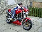
But I am left with a niggling issue that the hugger is not square from the back of the bike. I think it one of those issues that will be fixed (sometime/never) after it is "on the road".


Last edited by 350TSS; 27-04-2020 at 04:53 AM.. Reason: correction
350TSS is offline   Reply With Quote
Reply


Posting Rules
You may not post new threads
You may not post replies
You may not post attachments
You may not edit your posts

BB code is On
Smilies are On
[IMG] code is On
HTML code is Off

Forum Jump


All times are GMT. The time now is 05:13 PM.

vBulletin Skins by vBmode.com. Powered by vBulletin® Version 3.8.3
Copyright ©2000 - 2024, Jelsoft Enterprises Ltd.