UK Monster Owners Club Forum » .: Technical :. » Mods & How To's » Slow Monster rebuild

Reply
 
Thread Tools Display Modes
Old 27-11-2018, 08:07 PM   #1
350TSS
Too much time on my hands member
 
350TSS's Avatar
 
Join Date: Jan 2013
Location: Shipbourne
Bike: M900
Posts: 1,419
Proper winter now in darkest Kent, it never got above 4 degrees C today and a biting easterly wind so the garage is absolutely freezing. The insulated shed where I am now fibre-glassing was a comparatively cosy 10 degrees so that is where I have spent the last 2 days.
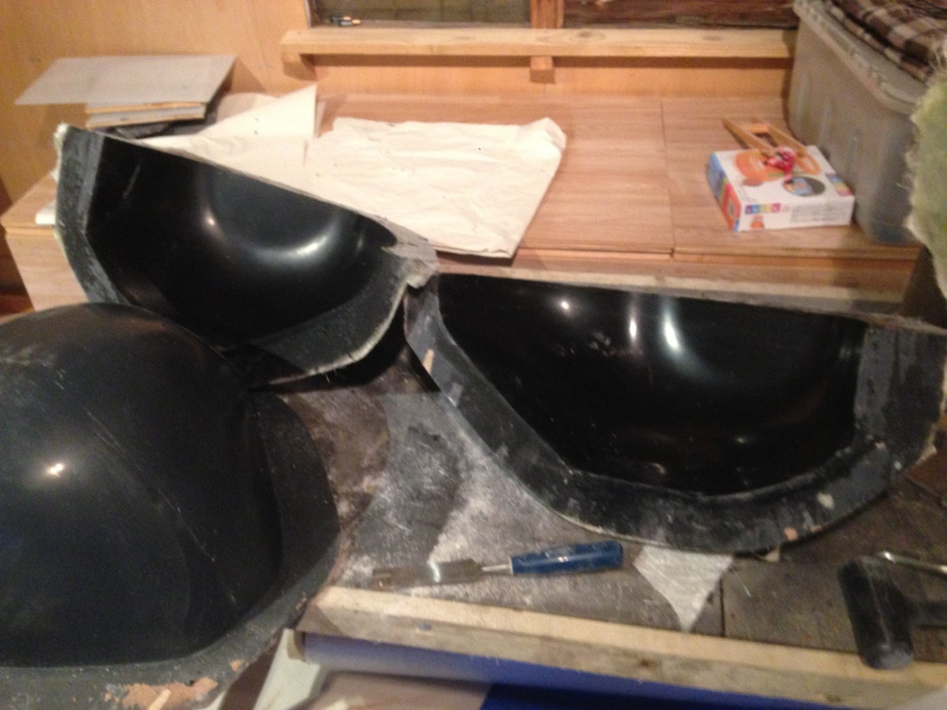
All the moulds that were damaged in removing them from the patterns have had two filling and rub down cycles. The belt covers will need a third. Unfortunately it is virtually impossible to get a polished finish on (mould repairing) filler inside a female mould particularly if there is any intricacy in the design. This means that I have a number of options when I come to make the actual carbon fibre component.
1) I put down a substantial gel coat (say 1.5mm thick as opposed to 0.5 to 1mm thick) and hope that I will be able to polish the top surface after it comes out of the mould, this suffers from the disadvantage that the gel coat is more brittle than the epoxy encasing the carbon fibre so could lead to vibration cracks, crazing /spidering of the finish downstream. Also I am not sure I want a carbon fibre showing through the gel coat as: a) it is not quite in keeping with the aesthetic I am trying to achieve (1970s café racer, 20 years before carbon fibre existed); b) it will require me to be skilled in laying and cutting the carbon fibre as I put it into the mould, if I get it wrong (90% racing certainty) it will look horribly home-made which of course it is.
2) As 1 above but put pigment in the gelcoat so the carbon fibre weave does not show through. Disadvantages: a) potential crazing of finish downstream due to excess gel coat thickness as above; b) it provides an additional complication to mixing the gel coat that is likely/could go wrong, too much or too little pigment causing colour variation between components: c) a slight loss of strength of the component – judged to be very marginal; and d) additional cost - the pigment is not cheap.
3) Do what I had originally planned to do and make the component and cover any post removal from mould defects with filler primer and paint.
On balance option 3 is best for me because it is cheapest, effectively kicks the can down the road with regard to obtaining an acceptable finish and allows me to get on with things tomorrow.
The next step for these moulds is time critical as the epoxy compatible gel coat has an optimum time to apply the epoxy/carbon fibre – 3 hours – too short and the carbon will intrude, too long and the bonding will be less than 100%. I will have to ensure that I have pre-cut all the carbon fibre for each mould on a day with sufficient available hours to complete all that I start that day.


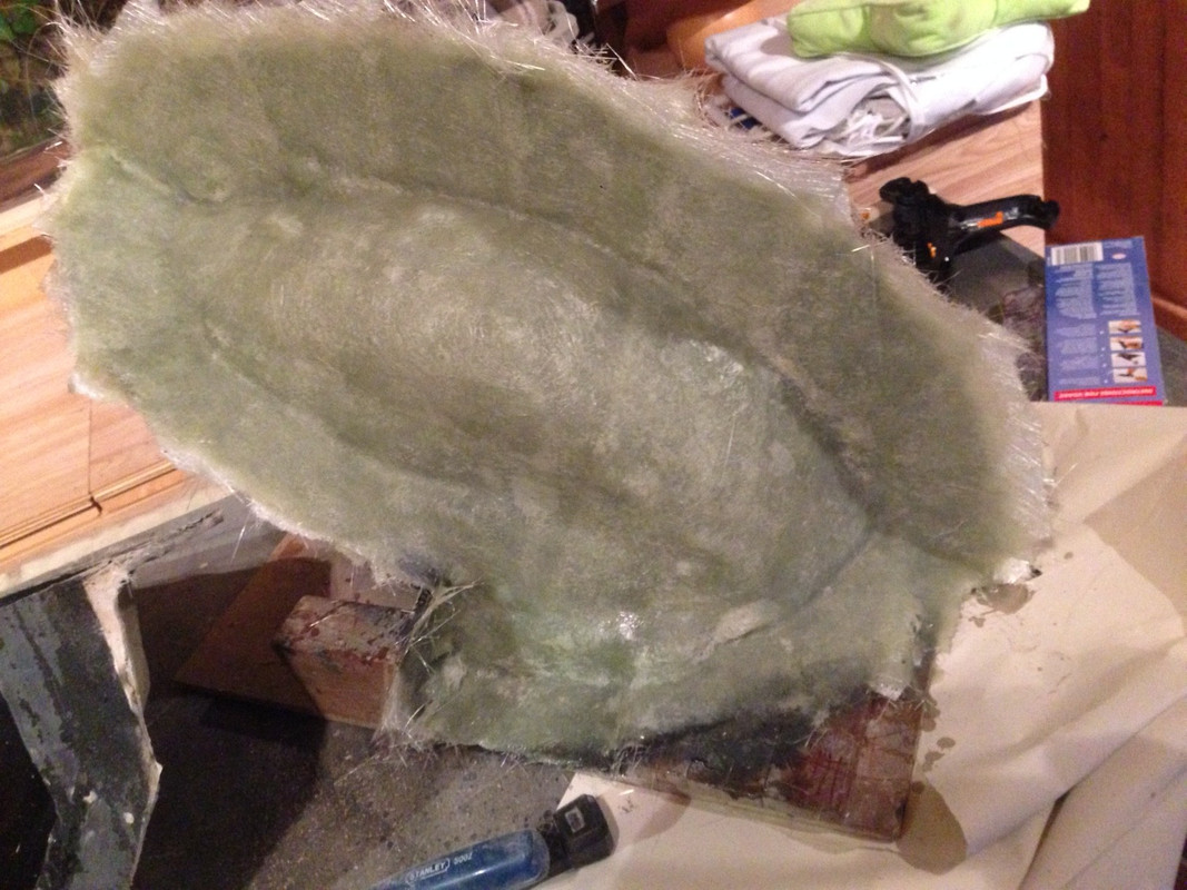
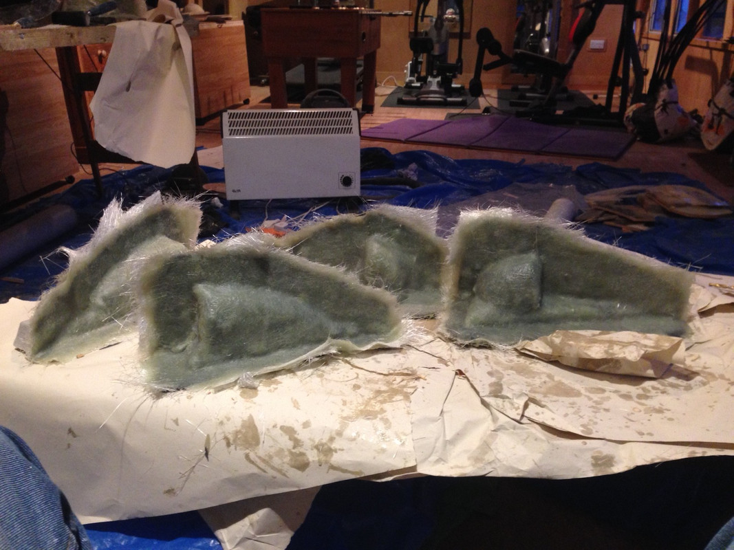
The rear hugger, the fly-screen and the ignitech enclosure have had the mould dividers removed which came off encouragingly easily. They are now ready for the second half of the process (5 coats of release agent, 2 coats of mould gel coat followed by a coupling coat with 100g mat, than 4 coats of 300g mat in polyester resin.
The air scoops have had the mould dividers attached with a hot glue gun, the edges and the divider interface will be sealed with wax and the divider given 5 coats of release agent.
The seat and the petrol tank, the most “in your face” components of the build have not yet got much beyond pattern stage.
More of the same tomorrow, I do feel as though I am making progress, slow but progress nevertheless.
350TSS is offline   Reply With Quote
Old 28-11-2018, 12:33 PM   #2
utopia
No turn left unstoned
 
utopia's Avatar
 
Join Date: Jun 2010
Location: leicester
Bike: M750
Posts: 4,545
Have you bought the carbon fibre cloth yet ?
If not, and if you're not wanting the carbon to be visible, you could consider using twill weave glassfibre instead.
I did this when I made my handguards.
The end result is just as thin and light as carbon would have been (its the resin that adds the bulk of the weight, I guess) and the appearance is the same once painted. Most folk think they are carbon actually.
I still used epoxy resin though.
And the glass cloth is significantly cheaper.
utopia is offline   Reply With Quote
Old 28-11-2018, 08:26 PM   #3
350TSS
Too much time on my hands member
 
350TSS's Avatar
 
Join Date: Jan 2013
Location: Shipbourne
Bike: M900
Posts: 1,419
Utopia thanks for thinking of my wallet unfortunately you are too late!

I bought 10m of carbon fibre about a year ago from Easy Composites, it was the weave most used for cosmetic applications and if I recall correctly was towards the top end of their pricing schedule.

About a month ago I did a little evaluation of how much I was actually going to need to complete all the components. I think the tank will take about 7 linear metres in all with the top, bottom and internal baffles (6 or 7 laminations). With the seat, rear hugger and fly-screen at 2 to 3 linear metres each, I have probably over provisioned when I ordered another 10m. This time however I bought what EC market as “black stuff” which is still carbon fibre but which has a small defect in the weave, and therefore cannot be certified for structural applications (F1 body tubs or suspension components etc.). It was about half the price. The intention was to use this for the second and subsequent laminations.

The moulds that were damaged when I took the patterns out were the belt covers, the rear sprocket cover, the headstock infill panels, the breather catch tank /chain oiler reservoir and the battery box. In total the area of carbon fibre I need to cover these components with 3 laminations would not be more than 0.5 linear metre.

With the exception of the battery box which will be hidden under the tank and behind the headstock I spent a lot of time and effort getting all the other patterns to a polished finish. I was extremely disappointed when the moulds were damaged as I knew that repairing them with filler was always going to show in the gel coat of the finished component as the gel coat picks up and amplifies the slightest imperfection and even the change in texture of the filler compared to the mould gel coat.
350TSS is offline   Reply With Quote
Old 29-11-2018, 06:07 PM   #4
350TSS
Too much time on my hands member
 
350TSS's Avatar
 
Join Date: Jan 2013
Location: Shipbourne
Bike: M900
Posts: 1,419
As a bit of light relief from rubbing down repaired moulds, I thought I would fit my heater pipe bungs to the float bowls and the blanking plugs for the electric heaters.
upload and share pictures
Whilst there I thought I would get rid of the “made of cheese” cross head screws on the carburettor float bowls and diaphragm top plus the choke retention clip. I used button head A2 stainless 5mm x 12mm screws which I then through drilled 2mm just because I did not want to go back into the resin fumed shed and it was comparatively warm in the garage today. This took about an hour then it was back to the rubbing down and second coat of gel coating the second half of the hugger, fly-screen and Ignitech enclosure moulds.
350TSS is offline   Reply With Quote
Old 29-11-2018, 06:17 PM   #5
350TSS
Too much time on my hands member
 
350TSS's Avatar
 
Join Date: Jan 2013
Location: Shipbourne
Bike: M900
Posts: 1,419
Note to self - need to make a proper bung for the slow running jet, just above the drain screw on the RH float bowl above - might try an aluminium turned part with a sealing "O" ring or casting one from silicon sealer. Both my 750SS and the 900 Monster have had a pair of carbs ruined by the original bungs going AWOL and the jet corroding / seizing and the brass head losing it's slot when trying to get them out.
350TSS is offline   Reply With Quote
Old 30-11-2018, 11:30 PM   #6
350TSS
Too much time on my hands member
 
350TSS's Avatar
 
Join Date: Jan 2013
Location: Shipbourne
Bike: M900
Posts: 1,419
Excellent day in the shed/garage today, lots of progress – not much of it photogenic.
I started by putting the throttle cable holder on an enforced diet. I looked at yesterday’s pictures and thought I could make the throttle cable holder a bit lighter.

Sometimes it is a bit obsessional.
Thereafter, it was coupling coat and 100g fibre-glassing the second half of the hugger, fly-screen and ignitech enclosure moulds, followed by sealing the air scoop moulds with wax and mould gel coating them.
350TSS is offline   Reply With Quote
Old 05-12-2018, 06:20 PM   #7
350TSS
Too much time on my hands member
 
350TSS's Avatar
 
Join Date: Jan 2013
Location: Shipbourne
Bike: M900
Posts: 1,419
Still bloody fibre-glassing!!
Today I managed to make some protectors for the pilot jets. The recess the jets sit in is more than 7.5mm diameter and the jet is about 7 to 8mm recessed. I toyed with a couple of ideas, a 3mm mini rawl bolt with an “O” ring that would compress against the walls of the recess (too difficult to make and not enough available depth), a cast plug made from silicone sealer (no improvement over the original rubber bungs)
I settled on tapping the recess 8mm, it was not possible to put the right size drill down there as I would have damaged the pilot jets but because the carburettor is comparatively soft I got away with starting a plug tap which had about a two thread lead in. So I cut one complete thread in each recess and then ground the lead in off the plug tap and managed to get 3 or 4 full threads before the tap hit the jet. Then I turned up some 10mm hexagon bar, threaded it 8mm and added a couple of 8mm ID “O” rings. Jobs a good un.
greenshot download
350TSS is offline   Reply With Quote
Old 06-12-2018, 08:40 AM   #8
mickj
Registered User
 
mickj's Avatar
 
Join Date: Jun 2018
Location: Clevedon
Bike: M1200s
Posts: 560
Great job 350TSS, wish I had a workshop like yours, and the skills.
__________________
Keep the rubber side down. Mick
mickj is offline   Reply With Quote
Old 06-12-2018, 08:39 PM   #9
350TSS
Too much time on my hands member
 
350TSS's Avatar
 
Join Date: Jan 2013
Location: Shipbourne
Bike: M900
Posts: 1,419
I did a bit more obsessive weight reduction today, as well as the usual.
The alternator lead gland nut, originally brass and 33g is now aluminium and 13g.
350TSS is offline   Reply With Quote
Old 07-12-2018, 03:28 PM   #10
350TSS
Too much time on my hands member
 
350TSS's Avatar
 
Join Date: Jan 2013
Location: Shipbourne
Bike: M900
Posts: 1,419
Another 23g saved today with the added bonus that the sump plug can be wired and the magnet inside the sump is strong enough to pick up a 2lb lump hammer whereas the old magnet can barely lift a 6mm open ended spanner.

Nearly finished the fibre-glassing of the fly-screen and the rear hugger, the 4 air scoops are now half done.
350TSS is offline   Reply With Quote
Old 07-12-2018, 04:28 PM   #11
Mr Gazza
Lord of the Rings
 
Mr Gazza's Avatar
 
Join Date: May 2013
Location: Norwich
Bike: M900sie
Posts: 5,834
Quote:
Originally Posted by 350TSS View Post
the magnet inside the sump is strong enough to pick up a 2lb lump hammer
Great way to collect lump hammers as you ride down the road... Hope the magnet doesn't fly out of the plug and stick to the crankshaft or a gearbox cog though!!!!
__________________
Mr Gazza is offline   Reply With Quote
Old 07-12-2018, 09:11 PM   #12
350TSS
Too much time on my hands member
 
350TSS's Avatar
 
Join Date: Jan 2013
Location: Shipbourne
Bike: M900
Posts: 1,419
The magnet is 12mm diameter and it is has a threaded 3mm stud on the back of its housing which goes about 10mm into the sump plug, I didn't dish the head of the sump plug bolt too much to avoid breaking through. The threaded stud is retained with Loctite, I would be very surprised (and disappointed) if it moved during use.
350TSS is offline   Reply With Quote
Old 11-12-2018, 07:22 PM   #13
350TSS
Too much time on my hands member
 
350TSS's Avatar
 
Join Date: Jan 2013
Location: Shipbourne
Bike: M900
Posts: 1,419
Today was a day that started very badly but ended up sort of OK.
I started by trying to separate the split mould from the pattern for the Ignitech enclosure. Fortunately. I remembered to drill the flange between the two halves of the mould so that it would register in the same place when I come to put the Carbon fibre and epoxy resin in, 4 x 6mm holes about 50mm apart. I then trimmed the borders with a dremel (using a c40mm diamond disc cutter) so I had a thin line between two coats of black gel coat on each half of the mould to aim at with the wood chisel. Horrendous quantities of evil dust were generated and even with a top quality mask I could taste it on my tongue.
The first setback was that the pattern separated from the base. For this I blame Gorilla glue which is in my humble opinion not a patch on Evo stik exterior wood glue (blue container). Then, although I had a distinct line to aim at with the chisel, the two halves just would not separate. My only option at this point was to chisel out the wooden pattern, which was made from marine ply covered in filler and hard gloss resin. Marine ply is made with the grain on each laminate at right angles to the one below it. Wood chisels are not great at cutting across grain. The wood was coming out in thin strands looking like pulled pork but with considerably more effort required.

Two hours later some of the pattern was still inside the mould and worse the filler had de-laminated from the wooden pattern and was proving very stubborn to remove.


In all honesty, I think the pattern was too intricate and whilst I did my best to shape it so there were no parallel sides I do not think I entirely succeeded and consequently the release agent on the pattern was not slippery enough to overcome the extent of mechanical locking caused by the shape and intricate details. Eventually I got it all out and there are about 4 or 5 places that will require repair where the chisel clashed with the gel coat.
Three lessons learned here, 1) use a really strong glue to attach the base to the pattern and if necessary mechanically fix with screws; 2) do not skimp on the width of the margin for the mould separator (min 50mm I had less than 25mm for the Ignitech enclosure) you cannot lay the fibre glass accurately to the edge of the margin so you will have to cut the margin back after all the fibre glass for the mould has hardened off; and 3)ensure that the gel coat is as thick across the whole width of the separator margin as on the main body of the pattern. The reason my mould would not separate was because the gel goat was less than 100% and the voids were replaced with the polyester resin applied with the first and /or second coats used to reinforce the mould. The release agent works exceptionally well on a smooth gel coat surface but substantially less well on a corrugated gel coat surface and almost not at all when the corrugated gel coat is contaminated with polyester resin.
350TSS is offline   Reply With Quote
Old 11-12-2018, 07:28 PM   #14
350TSS
Too much time on my hands member
 
350TSS's Avatar
 
Join Date: Jan 2013
Location: Shipbourne
Bike: M900
Posts: 1,419
When my poor old arthritic hands could take no more of wheedling out the marine ply ignitech pattern with a chisel I decided to have a go at the fly-screen, as with the hugger I left a good margin (75mm) and used my trusty Milwaukee jig saw (I love that tool) to trim the mould. 12 x 6mm register holes were drilled and about 6 chisels used to separate the mould. There were lots of cracking noises and quite a lot of trepidation as to the twisting force applied to the chisel to separate the mould from the pattern but in the end it was extremely satisfying. It separated with no chisel damage to the mould. Unfortunately, I will still need to do a couple of filler repairs where the gel coat either, took umbrage and refused to adhere completely to the pattern, or operator error occurred and an air inclusion was unaccountably in the gel coat.
which fallout is better

I had a look at my ETTC (estimated time to completion) on my Excel spreadsheet and despite the 3 hours overrun today getting the ignitech mould ready it has now dropped to below 250 hours – obviously it has got absolutely nothing to do with the time it will take me but satisfying progress nevertheless.
Tomorrow I hope I will have time to make the means of securing the air scoops to the frame – 12 x 40mm x 40mm x 1mm aluminium plates then drilled then shaped and bent and the gel coat on the other side of the air scoops and if I am feeling strong the separation of the hugger pattern from its mould. I have a strange feeling it will be more difficult than the fly screen because of the reverse angle half way along the bottom plane?????????????????

350TSS is offline   Reply With Quote
Old 12-12-2018, 07:32 PM   #15
350TSS
Too much time on my hands member
 
350TSS's Avatar
 
Join Date: Jan 2013
Location: Shipbourne
Bike: M900
Posts: 1,419
Well it is not often I get done all I plan to do, but today was one of them. Splitting the hugger mould took a good 2 hours as did making the air scoop brackets. Gel coating the other side of the air scoops took an hour, most of that time was getting a wax seal between the pattern and the base and applying 5 coats of release agent.
The brackets fit to the washers I welded to the inside of the frame via a 5mm screw, the washers will have rubber grommets fitted and a nylon P clip will hold the wiring harness parallel to the frame tube so entirely hidden from view and no cable ties evident. The three smaller holes in the bracket are to enable the bracket to be bonded to the inside of the air scoop


350TSS is offline   Reply With Quote
Reply


Posting Rules
You may not post new threads
You may not post replies
You may not post attachments
You may not edit your posts

BB code is On
Smilies are On
[IMG] code is On
HTML code is Off

Forum Jump


All times are GMT. The time now is 10:21 AM.

vBulletin Skins by vBmode.com. Powered by vBulletin® Version 3.8.3
Copyright ©2000 - 2024, Jelsoft Enterprises Ltd.