UK Monster Owners Club Forum » .: Technical :. » Mods & How To's » Slow Monster rebuild

Reply
 
Thread Tools Display Modes
Old 15-01-2020, 02:20 PM   #1081
Dukedesmo
Registered User
 
Dukedesmo's Avatar
 
Join Date: Sep 2010
Location: Leics
Bike: M900
Posts: 2,842
Quote:
Originally Posted by 350TSS View Post
I bought the SB offering and I will remove the extra oil seal on the blind side of the bearing before putting them back and I will press them into their machined space until the outer track "bottoms"
That leaves me with one more issue - how to press the new bearings in without damaging the quite fragile powder coating on the outside of the cap?????
I think removing the seal is the best (poss. only) way to do it? They come off easily enough though so not a problem - there are a few instances where Ducati use a single seal.

As far as fitting the bearings, I suggest you warm up the cap and freeze the bearing and it'll likely just drop in...
__________________
M900, 916, LeMans II.

Dukedesmo is offline   Reply With Quote
Old 15-01-2020, 02:58 PM   #1082
Mr Gazza
Lord of the Rings
 
Mr Gazza's Avatar
 
Join Date: May 2013
Location: Norwich
Bike: M900sie
Posts: 5,805
I tried the freezer method for the first time when I did the wheel bearings on the Norton.
I allowed my wife to have a couple of freezers in my garage, so there was a fringe benefit in this instance.
I simply put the new bearings in the freezer @-18 before I started the fannying with boiling water and so forth to get the old ones out.
By the time I had washed out the old grease and so forth ready to fit the new ones, the hub was only vaguely warm from the drenching with boiling water when I started.
The bearings had only been in the freezer about ten minutes but they dropped to the bottom of their housings with no bother and promptly locked into place. So you don't need to over do the freezing and warming thing to make a big difference.
__________________
Mr Gazza is offline   Reply With Quote
Old 15-01-2020, 05:40 PM   #1083
350TSS
Too much time on my hands member
 
350TSS's Avatar
 
Join Date: Jan 2013
Location: Shipbourne
Bike: M900
Posts: 1,419
Well lots of good proress today in less than a couple of hours.
First I fitted the oil seal into the clutch case, the one that that sits over the end of the crankshaft, went in a treat, pressed in with my thumbs with some red rubber grease.
The large seal red that sits around the gearbox input shaft was another story. It would not go in square and kept slipping out, eventually I managed to get it started but had to finish fitting it with a small soft faced dead blow hammer. This seal does not have a register to determine how far into the case it sits, so I had to guess how far to keep tapping it into the case.
The oil pump was then re-installed with new mating seals and then the clutch case was ready to fit.
After I had dosed the gasket faces with three bond and tried to fit it I realised that the big clutch seal was not into the case far enough as the outer lip of the seal was not quite over the edge of the large drilled boss on the input shaft (which the clutch basket bolts to). I had to push it about a 1mm further in for the seal to properly seat.
Next I fitted the gudgeon pin circlips using my home made tool, which did not work first time and needed a tweek with a file to radius the top corners of the SS grub screw. Thereafter it was perfect and took less than 30 seconds to fit each circlip.

thumbs up origin
Thanks for the advice above re bearing fitting.
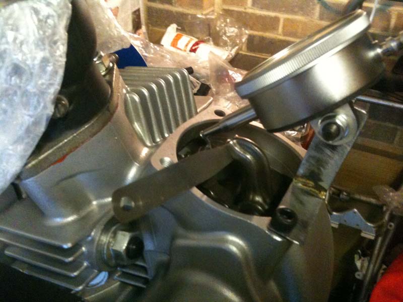
All the while this was going on the cam bearings with a seal removed from the blind side were sitting in the freezer and the cam bearing caps were reposing in front of the garage fan heater.
For the first one I started it with my thumbs then covered the outer surface with some plastic foam and popped it in the vice and squeezed it. I did not notice that the outer face is not square with the machining for the bearing housing so it ended up about half way in and about 3mm crooked.
This took about 20minutes with the dead blow hammer to get straight.
The second one was started with my thumbs then lightly tapped on the outer race with the dead blow hammer - so a result.
350TSS is offline   Reply With Quote
Old 15-01-2020, 10:01 PM   #1084
Luddite
Registered User
 
Luddite's Avatar
 
Join Date: Aug 2011
Location: Southampton
Bike: M1100evo
Posts: 2,465
That engine's looking beautiful, Richard.

Glad you managed to overcome your circlip hurdle too. Maybe Albie will be grateful for a loan of your circlip tool in due course...
Luddite is offline   Reply With Quote
Old 16-01-2020, 05:12 PM   #1085
350TSS
Too much time on my hands member
 
350TSS's Avatar
 
Join Date: Jan 2013
Location: Shipbourne
Bike: M900
Posts: 1,419
I planned today to get the barrels and heads on and then move onto cambelts and flywheel.
I spent the first hour getting the gasket faces top and bottom of the barrels spotless. The Haynes manual recommends a smear of gasket goo either side of the base gasket and also to grease the cylinder head studs (given the corrosion on the horizontal ones this seemed like a good plan).
Next I installed my new ring compressor and it worked a treat getting the three rings inside the vertical barrel with no dramas or cracking ring sounds. It took about 5 minutes, it was then I encountered a significant issue, with the oil control ring engaged in the barrel there was insufficient room to extract the tool, also the lugs that the ratchet pliers engage with would not go past the cylinder studs.
It was very messy for a while with copaslip and threebond gasket goo on every surface except the studs and the base gasket. Eventually I got it out and re-applied grease and goo.

Moving onto the horizontal cylinder I decided to try a Dukedesmo clone tool but a) I did not have a jubilee clip big enough ( this I solved by joining 3 jubilee clips) and b) I had no thin strip steel to slide under the compound jubilee clip (so I used some 1mm polypropylene).


I must have spent 3 hours trying to get the barrel down, the first two rings went in every time but the oil control ring just resolutely failed to engage.
I think it as a combination of issues that was making it difficult, 1. the three screw heads on the jubilee clip were just too large to fit neatly inside the the cylinder studs so the piston was always attacking the barrel at a very slight angle and 2. the polypropylene whilst excellent at sliding down the piston was just not quite stiff enough to deal with the oil control ring which is much less springy than the 2 compression rings.
I was very nervous about torquing the heads down as the last thing I wanted was to break a stud (although the studs probably break when hot through differential expansion of the alloy barrel and head and the SS stud).

Both heads torqued down was as far as I got today.

Last edited by 350TSS; 16-01-2020 at 05:26 PM..
350TSS is offline   Reply With Quote
Old 17-01-2020, 06:06 AM   #1086
jerry
Old Git
 
jerry's Avatar
 
Join Date: May 2006
Location: Cricklade
Bike: Multiple Monsters
Posts: 2,816
i have bought 2 blind puller sets over the years one was sealey the other generic and a slide hammer kit,, all a waste of money and now sold, none did the job of getting blind bearings out .
__________________
MONSTERMAN
jerry is offline   Reply With Quote
Old 17-01-2020, 04:16 PM   #1087
350TSS
Too much time on my hands member
 
350TSS's Avatar
 
Join Date: Jan 2013
Location: Shipbourne
Bike: M900
Posts: 1,419
A day spent removing historic corrosion, the belt pulleys were put away in plastic chinese takeaway boxes as they came off and when I came to fit them today they had not got any better for sitting in the boxes.
I used these
https://www.ebay.co.uk/itm/283582449034
They are quite effective but last no time at all and you seem to spend more time changing them than using them. Eye protection is essential.
When I fitted the pulleys to the jack shaft I was quite surprised by the amount of rotational movement of the pulley on the jack shaft. The woodruff key is in good condition and the keyway in the pulley is pristine (not worn or chaffed) but the pulley has about 1 degree rotational freedom.

Next I moved to change the 4 bearings on the moveable belt adjusters (2 bearings on each). The old bearings rotated freely enough but there was considerable corrosion on the outside which contacts the back of the belt. The bearings were very reluctant to move having corrosion between the post they sit on and the inner race. After about an hour they eventually succumbed to a combination of a Clarke bearing puller and a hammer.
Does anyone know whether these 4 belt adjustment bearings are/should be C3 specification?

I have 4 new non C3 bearings but do not want to fit them until I know which spec should be used.

I also fitted new fixed bearings, but before doing so thought I had better run a 8mm tap down all belt bearing stud holes. First because I had to weld nuts to original fixed bearings to get them out and second beause I painted the engine without protecting the stud threads.
One of the adjuster stud holes was extremely tight when the tap was inserted and when I came to remove the tap, I realised why. That hole had a thread insert which was unwinding out of its hole as the tap came out. Obviously a repair undertaken prior to my ownership. I managed to thread the insert back in and fixed it with some permanent grade loctite.
As usual not as much progress as I hoped when I started the day but we are creeping slowly towards the end game.
350TSS is offline   Reply With Quote
Old 17-01-2020, 05:28 PM   #1088
Luddite
Registered User
 
Luddite's Avatar
 
Join Date: Aug 2011
Location: Southampton
Bike: M1100evo
Posts: 2,465
I don't know if this helps, but Stein Dinse's alternative to the standard M900 bearings (70240691A) is this


i.e. SKF 6201-2RSH (no mention of C3 anywhere)
Luddite is offline   Reply With Quote
Old 17-01-2020, 05:29 PM   #1089
350TSS
Too much time on my hands member
 
350TSS's Avatar
 
Join Date: Jan 2013
Location: Shipbourne
Bike: M900
Posts: 1,419
Thanks mate - just the same as the ones I have in stock
350TSS is offline   Reply With Quote
Old 17-01-2020, 05:32 PM   #1090
Luddite
Registered User
 
Luddite's Avatar
 
Join Date: Aug 2011
Location: Southampton
Bike: M1100evo
Posts: 2,465
Result! .
Luddite is offline   Reply With Quote
Old 17-01-2020, 05:53 PM   #1091
Mr Gazza
Lord of the Rings
 
Mr Gazza's Avatar
 
Join Date: May 2013
Location: Norwich
Bike: M900sie
Posts: 5,805
Quote:
Originally Posted by 350TSS View Post
Obviously a repair undertaken prior to my ownership.
Ducati fitted inserts as standard, to the tensioner locking bolt threads.
__________________
Mr Gazza is offline   Reply With Quote
Old 18-01-2020, 02:29 PM   #1092
350TSS
Too much time on my hands member
 
350TSS's Avatar
 
Join Date: Jan 2013
Location: Shipbourne
Bike: M900
Posts: 1,419
Thanks Mr G
I got my 4 bearings onto the adjuster plates and thought it was about time to fit the belts. One slight problem though is that in removing the original rubber inside belt covers I have lost my datum marks for the belt timing.
Puzzling how to overcome this I found this interesting article:
http://www.ducati-upnorth.com/tech/camtiming.php

I have a degree disc and a dial gauge so I should be able to find TDC and the point of maximum lift of the cams provided I make up some sort of holding device above the valve stem. One thing I shall not be doing is re-setting all the valve clearances to 1mm and then re-setting them.
I bet you cannot wait for next week's exciting instalment.
350TSS is offline   Reply With Quote
Old 18-01-2020, 02:59 PM   #1093
Dukedesmo
Registered User
 
Dukedesmo's Avatar
 
Join Date: Sep 2010
Location: Leics
Bike: M900
Posts: 2,842
Quote:
Originally Posted by Mr Gazza View Post
Ducati fitted inserts as standard, to the tensioner locking bolt threads.
Mine has inserts for the pulley bolts (as do the ST2 cylinders lurking in my garage) so I assume that it was how Ducati did it originally? - makes sense to do so rather than relying on threads in the ally I suppose.

As for ring compression, as you said there isn't the room to get (most) proprietary tools in which is why I used the shim/jubilee setup which, if nice and oily works a treat and easy to remove once seated.

Nice to see the progress.
__________________
M900, 916, LeMans II.

Dukedesmo is offline   Reply With Quote
Old 19-01-2020, 05:10 PM   #1094
350TSS
Too much time on my hands member
 
350TSS's Avatar
 
Join Date: Jan 2013
Location: Shipbourne
Bike: M900
Posts: 1,419
SWMBO went to see my daughter at uni today so unuually for a Sunday I had a few hours in the garage.
When I had the exhaust made by MADASL I bought these off him (adjustable camshaft belt pulleys)


and after studying the the Ducati up North article I thought I may as well learn to use them and get my valve timing spot on rather than just setting them in ther middle of their adjustment and fitting them.

First job was to set up a timing disc so I cut a 13mm length of 25mm hex aluminium bar and bored it 17mm to fit over the crankshaft end to provide a flat base to mount the disc, an 8mm nut and bolt and some large penny washers secured it to the end of the crankshaft.

Next I cut a 95mm length of 15mm hex aluminium bar and interrnally threaded it 6mm both ends, installed a stud to attach to the crankcase and a short allen head bolt the other end to affix the pointer(made from a ground up penny washer).


To get the cam timing spot on (and the same for both cylinders) I need to find the point of maximum lift on the inlet camshaft and the only way I can think of doing this is with a dial gauge on the top of the valve stem (opening rocker valve cap).
There are two problems with this, first, the actual rocker almost completely masks the valve cap, I think I have got round this by making up a 30mm length of 15mm hex brass that sits on the outer extremities of the valve cap and still allows the rocker to operate. I drilled the hex brass 9mm x 20mm deep and angle ground out a slot to clear the rocker. I threaded the other end 4mm to allow me to screw in the pointer on the end of my dial gauge.

The second problem is that I need a secure and fixed position above the gasket face where I can fix the gauge. This needs to be directly above the valve stem so that I can measure the movement of the valve and needs to have a degree of adjustment so that the dial gauge can be positioned where it will record the maximum movement.


The trouble is the valve stem emerges above the gasket face at an angle of about 60 degrees to the gasket face. The mounting arrangement problem I have not yet solved.

I also managed to put the 4 bearings on the cam belt tensioners and as soon as I have worked out how to mount the dial gauge the belts can go on.
350TSS is offline   Reply With Quote
Old 19-01-2020, 06:27 PM   #1095
slob
.
 
slob's Avatar
 
Join Date: Jul 2003
Location: East London
Bike: Multiple Monsters
Posts: 9,710
I made up a stand for my dial guage (1) and a foot sit on the closer shim (6)

(5) is a piston stop that allowed me to accurately find tdc

feeler gauge is used to eliminate clearance during measurement.

a few minor differences between 900 & 1000 but the principles are the same
slob is offline   Reply With Quote
Reply


Posting Rules
You may not post new threads
You may not post replies
You may not post attachments
You may not edit your posts

BB code is On
Smilies are On
[IMG] code is On
HTML code is Off

Forum Jump


All times are GMT. The time now is 11:44 AM.

vBulletin Skins by vBmode.com. Powered by vBulletin® Version 3.8.3
Copyright ©2000 - 2024, Jelsoft Enterprises Ltd.