UK Monster Owners Club Forum » .: Technical :. » Mods & How To's » Slow Monster rebuild

Reply
 
Thread Tools Display Modes
Old 16-08-2018, 08:29 AM   #706
350TSS
Too much time on my hands member
 
350TSS's Avatar
 
Join Date: Jan 2013
Location: Shipbourne
Bike: M900
Posts: 1,419
With No 1 son away this week doing work experience I have been able to put in a little bit of Monster time.

Just the fly-screen and the tank to make mould dividers for now
350TSS is offline   Reply With Quote
Old 16-08-2018, 08:36 AM   #707
350TSS
Too much time on my hands member
 
350TSS's Avatar
 
Join Date: Jan 2013
Location: Shipbourne
Bike: M900
Posts: 1,419
I also got from the States a set of valve shims from EMS - nicely packaged and nicely finished. Not sure how the measuring device works but I am sure I will work that one out
These are not cheap at $293 and then the dreaded import duty of £63 but they will fit my 750SS as well .
Hopefully if the engine looks OK after I have bought tyres and a battery that will be the end of major expenditure and it will just about putting it all together. Touch wood on the engine!!!!!!
350TSS is offline   Reply With Quote
Old 16-08-2018, 07:43 PM   #708
350TSS
Too much time on my hands member
 
350TSS's Avatar
 
Join Date: Jan 2013
Location: Shipbourne
Bike: M900
Posts: 1,419
A bit more progress and views sought
Fly screen mould splitter.
screen shot windows
I was pondering the fitting of the rear wheel and realised that my CF wheels have no rear sprocket shock absorber in them (or do not appear to). Fine for a racing bike on a smooth track but local A and B roads mean you sometimes leave the seat and consequently the chain could get taught and slack in short order. Would a rear chain tensioning lever/roller alleviate the stress on the rear sprocket bolts?
350TSS is offline   Reply With Quote
Old 17-08-2018, 12:35 AM   #709
utopia
No turn left unstoned
 
utopia's Avatar
 
Join Date: Jun 2010
Location: leicester
Bike: M750
Posts: 4,545
Have a closer look.
The Dymag wheels do have a cush drive.
I may even still have an engineering drawing of the hub, if you're interested.
(I could probably work out how to email it to you)

Incidentally, I recently bought a Renthal sprocket for mine and it appears that the fitment is the same as (some ?) Kawasakis.
I have no idea if the cush drive design is the same though.
Anyway, said sprockets are available off the shelf, rather than to special order as I had expected.
.....which might be handy to know.
utopia is offline   Reply With Quote
Old 07-09-2018, 08:11 PM   #710
350TSS
Too much time on my hands member
 
350TSS's Avatar
 
Join Date: Jan 2013
Location: Shipbourne
Bike: M900
Posts: 1,419
Utopia - you are absolutely right, the hub did not look big enough to accommodate a cush drive, certainly not big enough for the monster size metalastic bushes - but it is there.
Been on hols so not much progress over the last month, but the kids are back at school now so some serious progress I hope will be made in the next month or so.
It did not however start well as a quite heavy item which has been retained on a high shelf in the garage shelf for the past 2 years by a bungee strap fell onto the tank pattern, denting it, not too badly but still required filling and re-primer-ing then top coating. Unfortunately the spray threw a wobbly and clogged resulting in a very orange peel top coat which had to be re-done. 2 days wasted. The bungee strap which was not over stretched just broke, nothing disturbed it, it happened in the middle of the night
350TSS is offline   Reply With Quote
Old 07-09-2018, 08:22 PM   #711
350TSS
Too much time on my hands member
 
350TSS's Avatar
 
Join Date: Jan 2013
Location: Shipbourne
Bike: M900
Posts: 1,419
Fed up with pattern making I decided today to make some other progress. The inner cam belt covers are rubber reinforced with a steel plate. The originals are perished/ broken/hardened with age, new ones on Stein Dinse website come out at about 45 Euros + P and P.

I wanted to make CF outer covers but the profile of the inner covers makes it a difficult pattern to make as they do not have a flat base.
I decided to have a go at making some aluminium base covers that would permit a flat based pattern and one piece covers each for the horizontal and vertical belts.
This was today's effort
350TSS is offline   Reply With Quote
Old 07-09-2018, 08:23 PM   #712
350TSS
Too much time on my hands member
 
350TSS's Avatar
 
Join Date: Jan 2013
Location: Shipbourne
Bike: M900
Posts: 1,419

350TSS is offline   Reply With Quote
Old 07-09-2018, 08:35 PM   #713
350TSS
Too much time on my hands member
 
350TSS's Avatar
 
Join Date: Jan 2013
Location: Shipbourne
Bike: M900
Posts: 1,419
I used 6mm aluminium plate cut with my trusty Milwaukee jig saw. I simply drew around the old rubber cover and drilled through it for the two retaining bolts. The camshaft boss was cut with a nearly right sized holesaw and filed to fit. The original rubber cam belt inner cover is about 12mm thick so i needed a spacer between the head and the new plate. My lathe had something in it mid job which I did not want to disturb so I found my smallest hole saw and cut holes in some off cut the 6mm plate and used the washer made by the hole saw as a 6mm spacer.
This will allow a flat pattern for the CF cam belt covers I will make.Two added bonuses are 1) that with the spacers they are 125g lighter than the rubber and 2) being spacers off the head there is mor room for circulation of air around the head, the original covers actually mask some fins.
350TSS is offline   Reply With Quote
Old 09-09-2018, 12:30 PM   #714
350TSS
Too much time on my hands member
 
350TSS's Avatar
 
Join Date: Jan 2013
Location: Shipbourne
Bike: M900
Posts: 1,419
Started on my patterns for the belt covers yesterday, using the old covers as a base. Unfortunately these were fire damaged when I tried to heat up the main drive pinion to get it off. Filed off the melted plastic (see the nibbles on the edges in the picture below)and then made a 1mm plate to fit the inspection cover plate. I need to work out how to make the raised edge along the top and bottom edges as without when it is moulded it will show up like a sore thumb.
350TSS is offline   Reply With Quote
Old 09-09-2018, 12:36 PM   #715
350TSS
Too much time on my hands member
 
350TSS's Avatar
 
Join Date: Jan 2013
Location: Shipbourne
Bike: M900
Posts: 1,419
I will do without the inspection plates on the finished article as I never used it when I was riding/commuting on the bike. The "nibbles" will be filled with body filler and the original plastic belt covers rubbed down to a polished finish rather than the existing mat finish.
350TSS is offline   Reply With Quote
Old 10-09-2018, 03:44 AM   #716
350TSS
Too much time on my hands member
 
350TSS's Avatar
 
Join Date: Jan 2013
Location: Shipbourne
Bike: M900
Posts: 1,419
Today's efforts, indents in the aluminium infill panel. I clamped the aluminium between two blocks of planed oak with a 0.5mm piece of shim metal underneath it and using another planed oak block aligned with where I wanted the indent. A sharp blow with a hammer and jobs a good one.
Also cut some off-cut polypropolene and evo stuck it to the belt cover to enable the filler to follow the contour of the cover.
how to screenshot on windows 7

350TSS is offline   Reply With Quote
Old 10-09-2018, 07:06 PM   #717
Jez900ie
Pleasantly surprised!
 
Jez900ie's Avatar
 
Join Date: Nov 2016
Location: Stoke on Trent
Bike: M900ie
Posts: 780
Clever stuff mate.
__________________
Monsters don't hide under the bed, they sleep inside the shed
Jez900ie is offline   Reply With Quote
Old 17-09-2018, 04:43 AM   #718
350TSS
Too much time on my hands member
 
350TSS's Avatar
 
Join Date: Jan 2013
Location: Shipbourne
Bike: M900
Posts: 1,419
Over the last couple of days I have tackled a job I have been putting off because I knew it was going to be a sod. My mark 3 brake hanger was needing some top hat bushes in steel to fit over the rear axle and inside an oilite bronze bush. I needed to final machine the external surface to a snug but rotating fit within the bush then part them off at an exact overall length 20.5mm. The length of the shoulder and also the brim was also critical a) to ensure no side play when positioned either side of the hanger plate and b) that the bushes were compressed together and not crushing the bronze bush.
I had previously found about 150mm of 42mm steel bar that I got in a plastic box when I bought the lathe. I have no idea what grade of steel it is, it is magnetic but does not appear to rust, it is very hard and when turned comes off in little chips rather than the satisfying spirals.
Using a carbide tipped cutter the external surface went relatively easily and successfully. All my parting off tools were HSS and they really struggled to make an impression, three parting off operations were needed to make two bushes. About every half millimetre of progress meant the tool had to be dismounted and ground sharp again. It took over 4 hours to complete the parting off operations and I was well pleased with the dimensional accuracy and finish although my arthritic hips and knees were complaining.
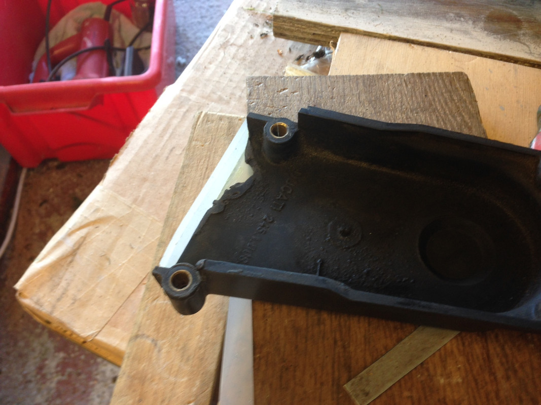
The next task was to install the bronze bush in the aluminium hub. I was able to push fit this in about half way by hand and remove it by hand with some difficulty. So about right the correct interference fit I thought. I popped it in the freezer for an hour then put it over one of the bushes and pressed it in with the vice. This took more effort than I thought should have been necessary. Sure enough when I came to fit the other side top hat bush it would not fit. I also noted that the oil within the bush had been squeezed out of the material and the inner face of the bronze was wet. I have never seen this before and knew that I was in for a long haul of scraping the bearing. Obviously my boring of the aluminium hub had been defective and the hole was a slight taper, maybe because I did not have the tool square in the tool post or the boring tool bar itself (about 8mm diameter) bending slightly as it was cutting deeper in the work piece.
It is now finished and put it on the scales it weighed a hefty 500g and this is without the spherical bearings and reaction rod and attachment plate to the engine, this will mean a net loss to my weight saving campaign of about 600g over the original fixed calliper mounting and at least half of will be un-sprung mass. I reduced the net loss by 30g by drilling 4 more 12mm holes but I think it will have to stay that way for now but will be one of those jobs that will niggle away and a lighter Mk 4 hanger bracket gets made at some point in the future.
350TSS is offline   Reply With Quote
Old 17-09-2018, 04:54 AM   #719
350TSS
Too much time on my hands member
 
350TSS's Avatar
 
Join Date: Jan 2013
Location: Shipbourne
Bike: M900
Posts: 1,419
A Mk 4 bracket will definitely be made as I am unhappy about the breakthrough of my original lightening holes into the hole where the aluminium hub fits and also the reduction in section at the point halfway between the calliper mounting holes and the pivot hole. If in the Mk 4 I rotate the hub through 45 degrees the the 4 threaded holes will be North/South/East/West on the hub hole and there will be more meat at the narrowest part. (if that makes sense). The lightening holes around the hub will be reduced from 10 mm to 8mm.
350TSS is offline   Reply With Quote
Old 17-09-2018, 12:51 PM   #720
utopia
No turn left unstoned
 
utopia's Avatar
 
Join Date: Jun 2010
Location: leicester
Bike: M750
Posts: 4,545
If the material you used was magnetic, resists rust and was a bastid to cut, it may well have been martensitic stainless steel (as used for brake discs).
Probably the most difficult stuff to machine that I've ever experienced .. worse than titanium in my experience.
Even worse, it tends to work-harden, so taking light, skim cuts becomes even more difficult as the material gets harder each time.

Also, the squareness of the tool in the toolpost will have no effect on any tapering of the hole .. this only depends on the lathe bed being parallel to the axis of the workpiece.
My toolpost has no positive indexing and I regularly set it out of square on purpose (with no resultant taper).

Given the hardness/toughness of the material, I would say that it is highly likely that deflection of the boring tool caused the taper.
The beefiest boring tool that fits the job and a change in material should result in a nicely parallel hole.
utopia is offline   Reply With Quote
Reply


Posting Rules
You may not post new threads
You may not post replies
You may not post attachments
You may not edit your posts

BB code is On
Smilies are On
[IMG] code is On
HTML code is Off

Forum Jump


All times are GMT. The time now is 02:48 PM.

vBulletin Skins by vBmode.com. Powered by vBulletin® Version 3.8.3
Copyright ©2000 - 2024, Jelsoft Enterprises Ltd.