The current can be recorded by inserting a ameter in series with the circuit, the current recorded will be lower if the systems pressure is less than the quoted specifications and higher if the flow of fuel is restricted in any way, for example: a blocked filter or a damaged fuel line.
When replacing a pump or filter care should be taken to keep the connecting hoses clean.
The systems pressure is the pressure that is seen within the system between the fuel pump and the pressure regulator, the system pressure is determined by the tension of a spring reacting against a diaphragm to which a valve plunger is attached, the relief pressure is set at a nominal 3bar, it is not adjustable. The diaphragm is referenced to atmospheric pressure on the spring side.
When the required pressure is obtained, the fuel pressure overcomes the pressure of the spring, the plunger lifts off its seat and excess fuel is returned to the tank.
This system due to the nature of its operation will automatically compensate for different fuel demands under different conditions. For example if the fuel requirement is low at engine idle, the plunger will lift and return a greater volume of fuel back to the tank than when the demand is higher, when a smaller amount of fuel is returned. The pressure regulation accuracy is dependant primarily on the quality of the spring and can vary between 2.75 bar to 3.25 bar.
The ECU does not have a fuel pressure input and assumes an injector inlet pressure of 3 bar when determining injector pulse widths, a higher pressure will cause more fuel to be injected thus richening the mixture, a lower pressure will weaken the mixture. It is also assumed that each injector delivers exactly equal amount of fuel. The injector contain a fine screen to catch any particles that could cause a blockage.
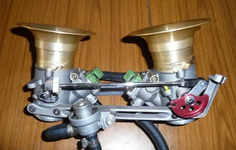
Throttle body assembly, the fuel pressure regulator is shown in the foreground.
The fuel tank filler assembly is divided into two parts, a base ring and the filler cap. The base ring fits into the tank opening and seals off the tank with an O ring, a second molded rubber ring seals the flange of the base ring to the tank preventing the ingress of water into the base ring cavity. The ring is secured to the tank by eight 4mm grub screws that screw into groove formed in the tank opening locking the ring firmly onto place. The cavity in the base ring will collect spilt fuel and water that can enter around the filler cap hinge plate. Any such fluids are drained through a hole to a hose that runs through the tank and exits to a wye fitting, the vent hose is connected to the other leg of the fitting the third hose exits below the engine.
It is necessary to remove the base ring in order to gain access to the pump and filter.
Base Ring

The hinged filler cap contains the vent valve, latch and lock barrel. The tank is vented to atmosphere via the filler cap which contains a check valve assembly that permits the escape or admittance of air into the tank but prevents the escape of fuel.
When the cap is closed, a hard rubber ring is pushed by four springs into contact with a ridge surrounding the tank inlet aperture effecting the closing seal. Closing the cap also seals the vent valve outlet against a rubber collar in the base ring, sealing the vent tube from the ingress of fluid and completing the vent path to the hose.
Underside of The Fuel Filler Cap

The vent check valves are contained within the filler cap, under the cover plate is a chamber at the base of which are the inlet and outlet ports. The chamber is at the highest point of the fuel tank and has access to the tank void via a small slot and by the generous clearance of the cover plate.