Test 1: Forward Bias of Positive Circuit Diodes
Put the meter's negative lead on the positive (red wire) terminal of the R/R. Then, put the meter's positive lead on all three terminals in turn of the alternator (yellow wire) connectors.
The meter should show a forward voltage drop of around 0.5V, which indicates that each diode is allowing current to pass (forward bias), and is therefore working properly. All three results should be approximately the same. (Note the variance from the left hand connector, which could indicate a problem.)
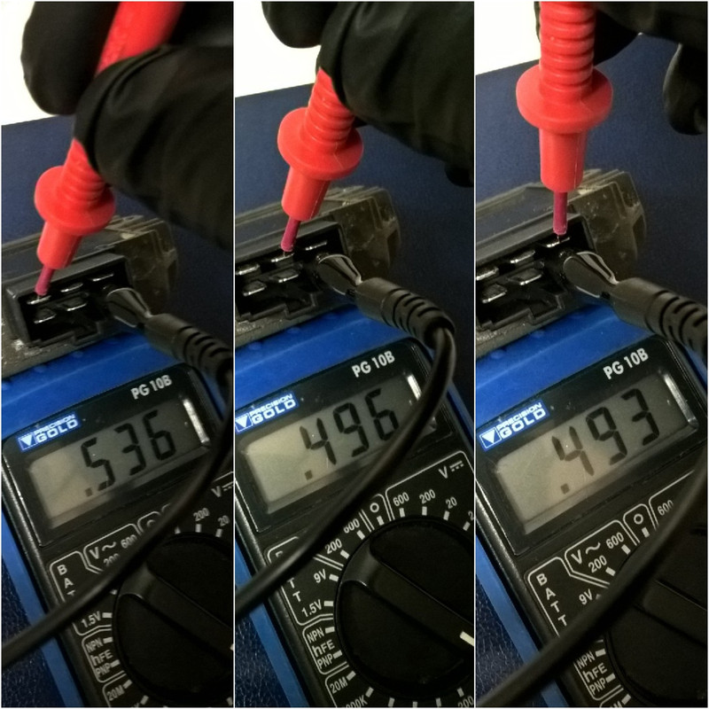 Test 1 results
Test 2: Reverse Bias of Positive Circuit Diodes
Test 1 results
Test 2: Reverse Bias of Positive Circuit Diodes
Put the meter's positive lead on the positive (red wire) terminal of the R/R. Then, put the meter's negative lead on all three terminals in turn of the alternator (yellow wire) connectors.
The meter should give a reading of "1." (on my meter), or "OL", (which stands for open loop), on some other meters. This shows that the diode is preventing current from passing back through (reverse bias), and is therefore working properly. All three results should be the same.
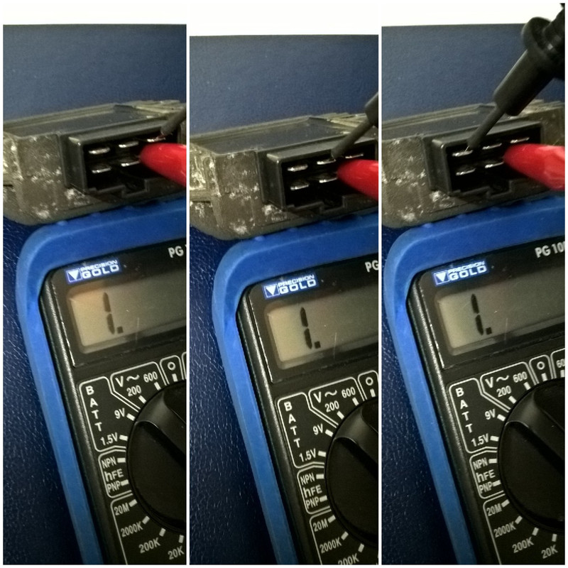 Test 2 results
Test 3: Forward Bias of Negative Circuit Diodes
Test 2 results
Test 3: Forward Bias of Negative Circuit Diodes
Put the meter's positive lead on the negative (black or green wire) terminal of the R/R. Next, put the meter's negative lead on all three terminals in turn of the alternator (yellow wire) connectors.
The meter should give a positive reading as in test 1, which indicates that each diode is allowing current to pass through. Again, all three results should be approximately the same.
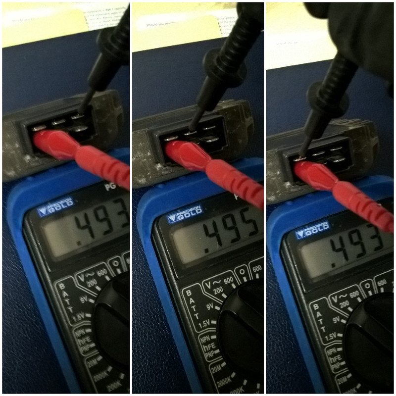 Test 3 results
Test 4: Reverse Bias of Negative Circuit Diodes
Test 3 results
Test 4: Reverse Bias of Negative Circuit Diodes
Put the meter's negative lead on the negative (black or green wire) terminal of the R/R. Next, put the meter's positive lead on all three terminals in turn of the alternator (yellow wire) connectors.
As in test 2, the meter should give a reading of "1." or "OL", which indicates that each circuit is open, and the diode is working properly by preventing current from passing back through.
If any of the forward bias test readings fail to show a voltage of around 0.5V*, or if any of the reverse bias test readings show a voltage, the diode has failed.
(*For comparison,I tested the new R/R and all six forward bias readings were identical at 0.520V.)
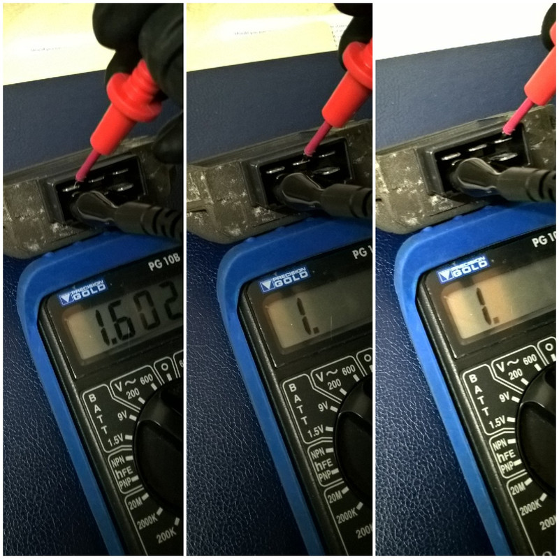 Test 4 results
In my case, the reverse bias test on the left contact showed a voltage, rather than the correct open circuit, indicating that the diode was shorted and therefore faulty.
A new R/R was fitted and, 'eccola!', back to a healthy 14.3V charging current.
So, if your battery is not being fully charged, don't automatically blame the alternator - check your rectifier too.